I should add - I don't like the Rega TT with it's standard felt mat on glass platter. A leather mat fixes that.
If I was to choose a starting point it would be epoxy Kevlar skins on a Nidaplast or similar core - both materials exhibit favourable self-damping properties. CLD could then be added to taste. Further, I would ensure that the upper and lower skins remain completely isolated from each other except by the core, ie. no through-bolts or potted inserts. The versatile composite skins add a further refinement of being able to 'build-in' CLD as required at the laminating stage. It never fails to amaze me that here we are in 2022 and DIYers practically never research or use composites. Gluing bits of wood together really is positively gramophone era!It's a foam core with phenolic layers. I saw one at a bargain price a year back and picked it up. It sounds very good. Different way of getting there.
Hugh

I think there is validity in lots of these comments, but i feel it all depends where in the chain things sit.Hi MrKlinky,
I think you make a valid point. I'd heard similar advice regarding loudspeakers cabinets years ago.
I think the Rega P6 plinth fits what you describe. True? It's a foam core with phenolic layers. I saw one at a bargain price a year back and picked it up. It sounds very good. Different way of getting there.
I'm hoping this heavy, highly damped approached sounds better yet, but we'll see.
Hugh
As i see it,
The stylus moves the cantilever as it traces the record.
If the cantilever mount had no stiffness or resistance then all the energy would remain in the cantilever/generator etc
The small resistance/stiffness of the cantilever mount (and the reaction in the generator?) transmit some of this energy as vibration into the cartridge body.
This is best transmitted away as easily and quickly as possible without resonance
Light stiff items achieve that best with as few joints and dissimilar materials as possible, avoiding reflection back of that energy/vibration.
So my arm and its mount concentrate on stiffness, mass growing gradually in the chain away from the stylus.
At some point it should be dissipated in some way by converting the energy to another form, perhaps as would happen in a damped material, where vibration turns to heat?
However, damped materials early in the chain seem to introduce distortion characterised as widening the test peak.
So, the plinth i am considering needs to dissipate that energy when it has got to there in the chain, that is what i believe CLD materials can do, whether they are better light or heavy or mixed, i am not sure. to be honest the measurements of my CLD avonite experiments are yet to be convincing........
Thats the thing with measurements, i am happy to let my ears be decieved but the measurements are less prone to self deception!
Self skinning foams are interesting materials..........Hi MrKlinky,
I think you make a valid point. I'd heard similar advice regarding loudspeakers cabinets years ago.
I think the Rega P6 plinth fits what you describe. True? It's a foam core with phenolic layers. I saw one at a bargain price a year back and picked it up. It sounds very good. Different way of getting there.
I'm hoping this heavy, highly damped approached sounds better yet, but we'll see.
Hugh
Those are interesting materials. Thanks.If I was to choose a starting point it would be epoxy Kevlar skins on a Nidaplast or similar core - both materials exhibit favourable self-damping properties.
Hi there, what is your set up please?If I was to choose a starting point it would be epoxy Kevlar skins on a Nidaplast or similar core - both materials exhibit favourable self-damping properties. CLD could then be added to taste. Further, I would ensure that the upper and lower skins remain completely isolated from each other except by the core, ie. no through-bolts or potted inserts. The versatile composite skins add a further refinement of being able to 'build-in' CLD as required at the laminating stage. It never fails to amaze me that here we are in 2022 and DIYers practically never research or use composites. Gluing bits of wood together really is positively gramophone era!
M
CD or files now - I moved away from vinyl as an inferior medium long ago!Hi there, what is your set up please?
M
OK, I understood, but there's no diy fun to be had there for me, so i am having some fun with vinyl. i have done some speakers. Fully corrected files i understand, but CD is surely a lossy format? off topic i knowCD or files now - I moved away from vinyl as an inferior medium long ago!
M
There is something I've wondered about in the light weight approach (like the Rega P6 and their more expensive skeletal designs like the RP9, etc). Is any performance lost in reducing the mass?If I was to choose a starting point it would be epoxy Kevlar skins on a Nidaplast or similar core - both materials exhibit favourable self-damping properties. CLD could then be added to taste.
Cat's Squirrel has a graph on this page. (I'm not sure that everyone will be able to see it.) It describes damping below resonance as "Stiffness controlled" and above resonance as "mass controlled".
https://www.tapatalk.com/groups/audioqualia/notes-on-plinth-design-t93.html
Thoughts anyone?
For the past few months, I had been thinking I would bolt everything through the two Corian layers. But MrKlinky's comment reminds me that this is not really taking full advantage of CLD.Further, I would ensure that the upper and lower skins remain completely isolated from each other except by the core, ie. no through-bolts or potted inserts.
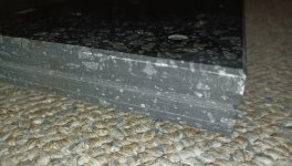
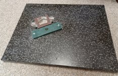
I recessed the hole for the bearing so that it only contacts the top layer (1st picture). The white circles were cut with a hole saw through the bottom layer only. Then they were glued back into place so as to contact the top surface. The white surround is a soft, stretchy caulking. This is an attempt to keep air from getting at the Ductseal between layers.
There's also a groove cut along the edge between the 2 Corian (actually Megalite Solid Surface) layers. This was later filed with a clear, soft caulking.
Attachments

A disclaimer...
Cats Squirrel has some concerns with a few of waveforms in some measurements I've made. If I was doing this for a living, I'd dig a little deeper figure out what's going on. But, time constraints. So take this for what it is - amateur effort with amateur test gear...
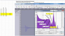
In posts 545 and 546, I had created some coupling between layers as an attempt to simulate the bearing attaching to both layers. Later, I repeated the measurements. This time the Accelerometer was attached to the top layer only. It was adhered using silicone grease and a sticky red tape intended for sticking Tyvek house wrap.
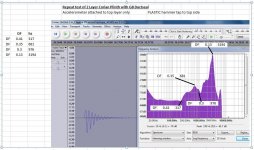
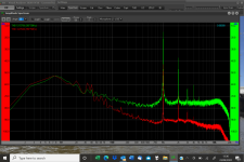
I picked 2 "typical" pulses from the lot. One was using the steel tip from the little Elf hammer. The second used the plastic tip. Here's the Spectrums and some measured Damping factors in a few spots. Both look good up to 1khz, so I'm very happy with this plinth.
Many thanks to Cats squirrel for his advice over the past year or so!
Cats Squirrel has some concerns with a few of waveforms in some measurements I've made. If I was doing this for a living, I'd dig a little deeper figure out what's going on. But, time constraints. So take this for what it is - amateur effort with amateur test gear...
In posts 545 and 546, I had created some coupling between layers as an attempt to simulate the bearing attaching to both layers. Later, I repeated the measurements. This time the Accelerometer was attached to the top layer only. It was adhered using silicone grease and a sticky red tape intended for sticking Tyvek house wrap.
I picked 2 "typical" pulses from the lot. One was using the steel tip from the little Elf hammer. The second used the plastic tip. Here's the Spectrums and some measured Damping factors in a few spots. Both look good up to 1khz, so I'm very happy with this plinth.
Many thanks to Cats squirrel for his advice over the past year or so!
Attachments
Applying Ductseal to the surface and clamping is a bit time consuming. So far, it's giving me the best results. Mostly, it seems to extend the damping into higher frequencies than other materials I've tried.
I did have another try with Corian and Blueskin (one sided adhesive) Butyl tape. This time I used a hard Urethane glue (Lepages PL) to stick the second layer of Corian. It was not so good.
I did see a few comments by Gedlee about adhesives for CLD in various places. He advised that it's the addition of fillers to the adhesives that make the difference. One is described here in post 532.
https://www.diyaudio.com/community/threads/the-best-cabinet-material.276721/page-27
For the past few months, I had been thinking I would bolt everything through the two Corian layers. But MrKlinky's comment reminds me that this is not really taking full advantage of CLD.
I recessed the hole for the bearing so that it only contacts the top layer (1st picture). The white circles were cut with a hole saw through the bottom layer only. Then they were glued back into place so as to contact the top surface. The white surround is a soft, stretchy caulking. This is an attempt to keep air from getting at the Ductseal between layers.
There's also a groove cut along the edge between the 2 Corian (actually Megalite Solid Surface) layers. This was later filed with a clear, soft caulking.
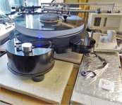
Looks good Hugh, what is the rest of the deck please?
What are current thoughts about what is connected to what.
I feel its fairly easy to conclude that if possible the motor should be as "unconnected" to the bearing, hence the platter and the arm base, but should the arm base and the bearing be tightly connected for synchronisation of any vibration between the two?
Mike
Thanks Mike,
The brown bracket you see in one of the photos is intended as a motor mount (initially). I have one of the standard (Primotek?) 120V ones used on Regas, my existing Heybrook TT2 and lots of others.
Later, I intend to rest it on a Sub plinth to "unconnect" it better from the main plinth. I'll try to measure the noise floor in both cases.
I have a bearing and Delrin platter from Tangospinner that I didn't photograph just yet.
I'm now experimenting to figure out the how I'll damp the Carbide rods for the LTA as well as a support structure for the rails. So, still a fair way to go.
Hugh
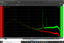
Excellent, interesting stuff Hugh, i spent today isolating the motor pod which is Origin Live to get rid of some 20 and 40 hz artefacts that were carrying across, i used some little sorbothane rounds i happened to have and thats done quite well, sufficient to expose that the next frequency to look at is the 50Hz which is hum from the wiring............if you look at the wee spike at the bottom you can see its 50 hz off the main spike either side and its evident in the full spectrum. if i cure that i will see the 20 and 40 again i am sure, an iterative process! mikeThanks Mike,
The brown bracket you see in one of the photos is intended as a motor mount (initially). I have one of the standard (Primotek?) 120V ones used on Regas, my existing Heybrook TT2 and lots of others.
Later, I intend to rest it on a Sub plinth to "unconnect" it better from the main plinth. I'll try to measure the noise floor in both cases.
I have a bearing and Delrin platter from Tangospinner that I didn't photograph just yet.
I'm now experimenting to figure out the how I'll damp the Carbide rods for the LTA as well as a support structure for the rails. So, still a fair way to go.
Hugh
Attachments
I should have added.......
I did have another try with Corian and Blueskin (one sided adhesive) Butyl tape. This time I used a hard Urethane glue (Lepages PL) to stick the second layer of Corian. It was not so good.
I did see a few comments by Gedlee about adhesives for CLD in various places. He advised that it's the addition of fillers to the adhesives that make the difference. One is described here in post 532.
https://www.diyaudio.com/community/threads/the-best-cabinet-material.276721/page-27
If "filler" is important in adhesives for CLD, I wonder if the same is true for tapes. 3M makes some expensive tapes for Vibration damping. Maybe they contain Butyl (or similar) along with lots of additives to create friction.
I'm guessing that's why the Ductseal works well compared to most of the other materials I've tried. It would be nice to find something economical that acts as a good adhesive as well as a Viscoelastic. I'm hoping to apply some of these techniques to speaker cabinets way down the road.
Nice work!Excellent, interesting stuff Hugh, i spent today isolating the motor pod which is Origin Live to get rid of some 20 and 40 hz artefacts that were carrying across, i used some little sorbothane rounds i happened to have and thats done quite well, sufficient to expose that the next frequency to look at is the 50Hz which is hum from the wiring............if you look at the wee spike at the bottom you can see its 50 hz off the main spike either side and its evident in the full spectrum. if i cure that i will see the 20 and 40 again i am sure, an iterative process! mike
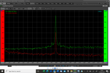
Everything is always a prototype here Hugh, so i cut away the motor pod part of the plinth and supported it directly from the wall shelf with an inner tube and sorbothane polos in between, as per pic, this further tidied the 0-100hz peaks and improved the signal spike as per these new measures as attached
Attachments
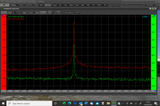
Mike,Everything is always a prototype here Hugh, so i cut away the motor pod part of the plinth and supported it directly from the wall shelf with an inner tube and sorbothane polos in between, as per pic, this further tidied the 0-100hz peaks and improved the signal spike as per these new measures as attached
Thanks for posting that. Do you notice any difference subjectively from the change?
What's your platter made of? Is the record directly on the platter, or do you use a mat?
Hugh
- Home
- Source & Line
- Analogue Source
- DIY CLD Plinth Design--A measured Approach