Rod, you need to look at the Build Guide. The rectification and smoothing is done on the speaker protector board. You need to feed it AC. 6 or 12 VAC depends on the relays you are using.The diyaudio speaker protection accepts 12vac? I assumed it was 12vdc. Does the DC speaker protection boards from the group buy, do they require 12vac or 12vdc?
J
I'm curious how much power you need. Also curious what you're using the standby supply for. Just so I can better understand the end application, that's all.Indeed, Neurochrome's soft start is Rolls Royce. All features you could think of and max 2kVA transformer. A beefier standby supply is about all I would want (0.5W is a tad weak). Adjustable LED brightness is a very nice touch.
Tom

Thanks, makes sense!Rod, you need to look at the Build Guide. The rectification and smoothing is done on the speaker protector board. You need to feed it AC. 6 or 12 VAC depends on the relays you are using.
J
Some progress yesterday. I configured the DIYaudio soft start, 2x Antek transformers (stacked on top of each other), and 2x DIYaudio PSU (also stacked on top of each other) with the success for end result of +/- 71.5VDC! I haven't figured out why the -71.5VDC side of each PSU won't light the LED, maybe I installed it backwards? I can't wait for the new boards to be delivered!

@jjs For the speaker protection boards in the group buy is IXTH130N20T a suitable replacement for IRFP4668PBF? IRFP4668PBF is out of stock on Mouser. Here is IXTH130N20T: https://www.mouser.com/ProductDetail/IXYS/IXTH130N20T?qs=6UKyFUzHTllvsxEXCJ2L5w==
Also, I am looking for an alternative for the optocouplers TLP591B as they are also out of stock on Mouser.
Also, I am looking for an alternative for the optocouplers TLP591B as they are also out of stock on Mouser.
Any suggestions on where to source good signal input wiring? I watched Daniel's wiring video again and the closest thing I find on Amazon is the following, does it look alright?
https://www.amazon.com/Conductor-Shielded-Stranded-Spindle-Transmission/dp/B0D9JWWGKT
https://www.amazon.com/Conductor-Shielded-Stranded-Spindle-Transmission/dp/B0D9JWWGKT
Im thinking potential builders. Largest wolverine PSU is 2kVA 60VAC. But yes, we know no one needs that power.I'm curious how much power you need. Also curious what you're using the standby supply for. Just so I can better understand the end application, that's all.
Tom
I'm not certain what the Wolverine Team thinks about this, but AWG 18 seems very heavy for signal wiring to me. I'm using a much lighter gauge Mogami cable that is shielded. In the U.S. check out Markertek. They sell to the broadcast industry. They have Belden, Mogami, Canare all sold by-the-foot for reasonable prices.Any suggestions on where to source good signal input wiring? I watched Daniel's wiring video again and the closest thing I find on Amazon is the following, does it look alright?
https://www.amazon.com/Conductor-Shielded-Stranded-Spindle-Transmission/dp/B0D9JWWGKT
Stop using giant cigar sized patch cables inside your beautiful hand crafted, metal, shielded amps and preamp projects.Any suggestions on where to source good signal input wiring?
Stop The Insanity - Susan Powter (Just Google her or see YouTube)
Go with a 1533 28AWG or similar. Keep it simple and small and pretty looking.
Giant cigar cables are for Woodstock in the mud and Speak On speaker connects.
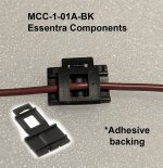
May I suggest you use a clamp like the *MCC-1-01A-BK?
*Use a tiny drop of high temp epoxy glue with these little cable clamps to keep them in place but do so with caution. Not easy to change after the fact without leaving cosmetic damage.
You can buy 1533 shielded cable anywhere for dirt.
Attachments

But your concerns about power delivery were about the standby supply (5 V @ 100 mA). I'm just wondering what you're driving with that supply that would require significant amounts of power.Im thinking potential builders. Largest wolverine PSU is 2kVA 60VAC. But yes, we know no one needs that power.
Tom
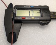
1. From the main heatsink to the top of the new input capacitors is 37mmhave the dimensions of the heat sinks
2. From the main heatsink to the top of the IPS heatsink is 53mm
3. From the main heatsink to the top of the Pre-Driver heatsink is 42mm
4. From the main heatsink to the top of the EF3-3 or EF3-4 Driver heatsink is 62mm
Thanks Stuart!1. From the main heatsink to the top of the new input capacitors is 37mm
2. From the main heatsink to the top of the IPS heatsink is 53mm
3. From the main heatsink to the top of the Pre-Driver heatsink is 42mm
4. From the main heatsink to the top of the EF3-3 or EF3-4 Driver heatsink is 62mm
Looks like everything will fit inside the slightly larger version of the chassis even with the bigger shielded transformers.
When I'm done modeling everything I'll post up all the STEP files for everyone to use. At least for the universal components.
Last edited:
Belden cable. Get shieled twisted pair or triad. Its all we will use at work since its the only wire we have NEVER had an issue with. 22awg should be sufficient and even oversized a bit.Any suggestions on where to source good signal input wiring?
Any suggestions on where to source good signal input wiring? I watched Daniel's wiring video again and the closest thing I find on Amazon is the following, does it look alright?
https://www.amazon.com/Conductor-Shielded-Stranded-Spindle-Transmission/dp/B0D9JWWGKT
Canare L-2T2S Balanced Cable
Check my build album photos.IPS board completed......let start with the Outboard before test all

Very nice looking board, super neat. I know how much work it takes to build one like that well done.IPS board completed......let start with the Outboard before test all
Just double check those flecks are dust and not solder.
I would recommend that you dont put the second transformer adjacent to the input stage area at the back panel of the chassis.Thanks Stuart!
Looks like everything will fit inside the slightly larger version of the chassis even with the bigger shielded transformers.
When I'm done modeling everything I'll post up all the STEP files for everyone to use. At least for the universal components.
View attachment 1480248
Perhaps consider one larger transformer or two stacked transformers towards the front panel area of the chassis where the less sensitive area of the amplifier is.
The bulk capacitance can go towards the centre/back panel. This layout has proven to be successful in many amplifier builds.
Hope this helps, just trying to save you some dramas
-Dan
Hi Rodimus, for signal wiring I used shielded twisted pair and there are many iterations of it around, it is commonly used as XLR cable.Any suggestions on where to source good signal input wiring? I watched Daniel's wiring video again and the closest thing I find on Amazon is the following, does it look alright?
https://www.amazon.com/Conductor-Shielded-Stranded-Spindle-Transmission/dp/B0D9JWWGKT
Stuarts post above shows and describes the method. See Canare L-2E5 (twisted pair) or L-4E5 (star quad) both are shielded flexible mic cables.
You dont have to go crazy with the wire gauge. There are some nice star-quad with a a braid floating around now but realistically it is only a few cm to the input of the amplifier anyhow and shielded twisted pair is sufficient.
-Dan
- Home
- Amplifiers
- Solid State
- DIY Class A/B Amp The "Wolverine" build thread