What is wrong with this siglent for 300€ https://www.siglent.eu/product/1139233/siglent-sds1202x-e-200mhz-dual-channel-oscilloscope

I found here in my city
Some genuine sanyo 2sa1380/2sc3502
It is 200v operating voltage,
So they must be replacements.
Does he have them? someone try
Thanks
Some genuine sanyo 2sa1380/2sc3502
It is 200v operating voltage,
So they must be replacements.
Does he have them? someone try
Thanks
Hi David,
It takes familiarity with test equipment and both types of oscilloscopes to know. What's wrong? Well, look at DSO specs, but read papers by Keysight and Tektronix. In addition, there is nothing like actually trying them out.
Take a hint from this. I've used test equipment including oscilloscopes for over 50 years now (I started young with my own). I have some expensive new equipment and some older analogue types. I keep the analogue types. Any guesses as to why? If all I did was amplifiers and preamps, CD players I would not have a digital scope. Hmmm, must be a reason that doesn't have to do with money at play here.
Thanks Mainframe.No issue. They won't light, because you removed (and please confirm) the temporary parallel resistor on R17
I used a R17 for initial testing [30DCV 0.3A].
2nd round with output transistors, J103 and R17 removed, the two IPS Led's don't light up.
3rd round with full power, all Led's light up.
Got it
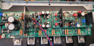
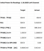
Been a good day. I have completed initial test with output transistors @ 30DCV / 1A. After 20 minutes bias held at 40mV.
I guess I'm ready for a full power test.
Thanks to all who have pushed me to this point.
I guess I'm ready for a full power test.
Thanks to all who have pushed me to this point.
Attachments
Hi Gianluca,
I am building a Wolverine EF3-4 (V4.2) with the following (2 x 8) output devices:
The 2 EF3-4 boards are 34.5 cm long. Do you think they will fit into the new MiniDissipante 5U case, and include an SMPS MicroAudio Cobra-S2 (27 × 12.5 × 6.5 cm)?
Output onsemi MJL4281 MJL4302 TO-264
Can the Wolverine TO-264 drill pattern be drilled into the heatsinks?
Or is there a better option right now?
Regards,
Wouter
Hi Wouter,
If the drill pattern is the same we have done in the past for our 5U 400 chassis then yes since the heatsinks are the same
Hmmm.
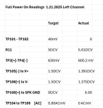
Full power test today. all LEDs working.
See measurements below, all on target except for biasing. After my 30DCV 1A test on Sunday, I dialed down R109 to the point where there was no reading, but not all the way down in preparation for today's test.
Today I dialed R109 up quite a ways and saw no reading on my DMM @ mV. I didn't dial it all the way and stopped to assess. I feel I turned it sufficiently to start to see a reading. I checked that the leads were in the correct place and good connection. I use my Fluke 87 for this measure. I didn't swap it out for a different DMM. I can try that. Or I can go back to the Rigol 30DCV /1A test where I achieved 40mV reading and see if I can duplicate it there.
Just don't want to blow anything at this point.
Appreciate all insights or suggestions.
So close.
Attachments
Show a picture of where you are measuring. That pot is a 20 turn pot. You may need to go futher. When you get to the end of it's travel it will make a very faint clicking sound.
Hey guys. I've had a change of mind or may be not. I'm going to need a preamp with this that will have multiple inputs and may be a phono stage. I know there are loads of kits available. But I'm after one on a par with the Wolverine. The idea is to eventually get rid of my aging Yamaha receiver RX-V667. I'm thinking of doing a preamp first as I'm feeling it may ease me
( hahaha yeah, things don't always work out that way.🤣) back into DIY. Any of you guys can point me in the right direction please?
I suppose it doesn't matter which one I build first.
Cheers
Tony
( hahaha yeah, things don't always work out that way.🤣) back into DIY. Any of you guys can point me in the right direction please?
I suppose it doesn't matter which one I build first.
Cheers
Tony
The amplifier will probably be cheaper and easier overall. The preamp has a lot of moving parts, especially if you want it to have a remote.
Hi Tony,
The Wolverine is an extremely high quality amplifier, easy to drive. So, what matches it would be an equally high quality preamp with low noise and distortion. This could be an IC based design, or transistor type. You're going for the best performance and lowest noise. You'll have to have very low noise power supplies to go with it.
Remote controls are overrated and some remote systems compromise performance. The difference between a good DIY preamp and the Yamaha is not subtle, you would never go back.
You can go with the Iron Pre for sure! I built the Wolverine first and then the Iron Pre. Sound is really good!Hey guys. I've had a change of mind or may be not. I'm going to need a preamp with this that will have multiple inputs and may be a phono stage. I know there are loads of kits available. But I'm after one on a par with the Wolverine. The idea is to eventually get rid of my aging Yamaha receiver RX-V667. I'm thinking of doing a preamp first as I'm feeling it may ease me
( hahaha yeah, things don't always work out that way.🤣) back into DIY. Any of you guys can point me in the right direction please?
I suppose it doesn't matter which one I build first.
Cheers
Tony
Gaetano.
Thanks guys. Much appreciated. Now to find the iron Preamp. Is there a build thread?
Cheers....Tony.
Cheers....Tony.
Go to the DIYA store, look under the Projects and click preamps.
https://diyaudiostore.com/pages/project-iron-pre
Easy build and dead silent background. Sweet pre!
https://diyaudiostore.com/pages/project-iron-pre
Easy build and dead silent background. Sweet pre!
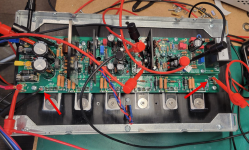
See leads on TP 101 and TP102.Show a picture of where you are measuring. That pot is a 20 turn pot. You may need to go further. When you get to the end of it's travel it will make a very faint clicking sound.
Knowing that I had already turned the R109 pot to maximum value last night, I decided to turn the pot to the end or maximum value. But after 30 plus turns I gave up because I did not hear the faint clicking sound. This is weird.
I will replace it and return to testing with the Rigol at 30DCV 1A to ensure it is functioning before returning to full power.
Am I missing something?
Attachments
Is the meter set to DC or AC volts? Should be DC millivolts if it has that scale. Also check your meter with a 1.5V battery to make sure it is working correctly.
You mentioned you removed R17. You're not being clear enough. Did you remove R17, or did you remove the temporary parallel resistor that is placed on R17 for low voltage testing.
For clarity
For 30V low voltage testing: You should have R17 installed (as BOM, matching the chosen rail voltage), and you should have a temporary parallel resistor installed on it.
For full rail voltage: you should just have R17 installed, and no parallel resistors.
Since you are getting good results at 30V, and no bias voltage at full rail voltage, I'm not sure if for full rail voltage testing you A) completely removed R17 in error, or you B) left the parallel resistor in accidentally. I cant see R17 in your picture above, but it may be obscured by the VAS heatsink
Sorry for my lack of clarity.
Only R17 is installed.
I can hear the faint clicking on the pot at the maximum value end.
I plan to retest at 30DCV today to confirm that R109 is working. I will keep track of full revolutions of the pot.
If so, I will return to full power testing.
Only R17 is installed.
I can hear the faint clicking on the pot at the maximum value end.
I plan to retest at 30DCV today to confirm that R109 is working. I will keep track of full revolutions of the pot.
If so, I will return to full power testing.
This is a long shot. Sometimes those clip on lead fail. It might be worth checking another location like the rail voltage to confirm they are ok and your DMM is set correctly.Am I missing something?
- Home
- Amplifiers
- Solid State
- DIY Class A/B Amp The "Wolverine" build thread