
So that it lasts forever, you may as well get a stainless bolt.
Imo of course but you may as well use exclusively stainless fasteners in an amplifier.
Save some poor sod the joy of corroded bolts when it needs servicing in a couple of decades.
Built it to last forever unlike most modern drek.
Imo of course but you may as well use exclusively stainless fasteners in an amplifier.
Save some poor sod the joy of corroded bolts when it needs servicing in a couple of decades.
Built it to last forever unlike most modern drek.
Last edited:
Yes, there is no significant difference. - (4th GB BOM) you must either install all [C123,124,125,126 270uF THT and 121,122 0.1uF SMD caps] OR [C123,124 270uF THT, C121, 122 0.1uF as THT poly's and ignore C125,126 THT]. Either will work.Hello,
I am close to finishing building a Wolverine with EF3-4 from the 4th group buy. Everything is going well this far but I have a question about C125 and C126. In earlier versions they weren't in the schematic. Will it be any significant difference if I skip these capacitors? For the moment I do not have the SMD capcitors for C121 and C122 but have the through hole versions that mounts in the same place as C125 and C126.
It's in the build queue.Sad face , interested in a Wolverine?
I got in on the first group buy.
Probably a couple of years away at my current rate of building.
Getting close, all auxiliary boards built. Almost time to start wiring it up 🙂

Go for it Dolamike, looks like the makings of a nice amp right there
diyAudio
 This project is a Group Buy. The public group here must agree - in this thread - on what parts will be sold, by whom, and where. Members must abide by those agreements. Any regular sales of the Group Buy PCB, kits or other specific related items outside of diyAudio or this thread will result in the removal of that person from diyAudio.com This is completely at the discretion of the Moderation Team.
No one shall send unsolicited or blind sales PMs to anyone else on the forum. This has long been against the rules and will also result in the immediate banning of any person...
This project is a Group Buy. The public group here must agree - in this thread - on what parts will be sold, by whom, and where. Members must abide by those agreements. Any regular sales of the Group Buy PCB, kits or other specific related items outside of diyAudio or this thread will result in the removal of that person from diyAudio.com This is completely at the discretion of the Moderation Team.No one shall send unsolicited or blind sales PMs to anyone else on the forum. This has long been against the rules and will also result in the immediate banning of any person...
- stuartmp
- Replies: 126
- Forum: Group Buys
See the group buy thread in the group buys section of the forum. First post has all the details.I am located in Spain. Where is the nearest place for my to buy the pcb’s?
Thanks, below is what I’m building…Looking schmick 😎 what rail V/pres/drivers/outputs you go with
Hi guys,
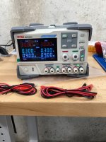
I need to order a couple of resistors for both the IPS boards and the power boards and then I am ready to test. I'll be powering up with my new linear bench power supply, the UNI T DPO3303A. I had been using a variable transformer and a dim bulb tester that I built. Looking forward to powering up under controlled conditions.
John
Attachments
I am looking for some pairs, 2SC4883A + 2SA1859A sanken
Does anyone ? know where I can find genuine ones.
Thanks
Does anyone ? know where I can find genuine ones.
Thanks
Hey all, I'd love some perspectives on wiring the 4-3 in a 4U case, any help or comments here would be greatly appreciated.
I've been doing some mockup and just realized that the ideal wiring examples from the build thread seem to be in a 5U case... I unfortunately have a 4U. This leaves me with just a bit less room vertically on my heat syncs. I'm having to maybe group my power and speaker out wires more closely or find a way to run the speaker out at the opposite side. Neither options seem ideal. Images below.
Any help appreciated. Thanks.
I went with your top option - speaker cable along bottom of chassis, away from PCB. Here's the self-noise measurement of the E1DA ADC followed by the noise measurement of 1 channel input shorted


Just like to thank Stuart and the Wolverine team for this great amp.
Also to Fire for parts and Mainframe for his grounding recommendations.
I made a mistake of installing a diode from the ops board, reached out to Stuart for his assistance and never hesitated to offer his expertise.
After rectifying the issue, Stuart and Mainframe continued to support with proper wiring techniques to achieve zero noise.
The amp sounds great.
Clean, great depth, detailed musical separation at all volume levels.
Regards
A little more progress to share. I've been doing final planning and preparation. I drilled and built the front and back panels. The back panel was quite a bit of work, I'd recommend buying the pre-drilled back panel if there are any new builders reading. I also did some mockup, i think I will elevate the power supply and put the bridge rectifiers underneath. That seems to help create a nice tidy layout. Lastly I have built the quasimoto test rig. I'll be testing my transformer this week and placing my (hopefully) last parts order. Looking forward to assembly. 🙂
Question to the forum, does anyone have a photo example of placing a point to point snubber directly on the bridge rectifier? I'd love to see how people have implemented that in the past. Any help would be greatly appreciated.
Thanks again to the wolverine team and this forum, really fun and interesting project. I'm learning so much!
- Home
- Amplifiers
- Solid State
- DIY Class A/B Amp The "Wolverine" build thread