

It's fine to announce things from the Build thread to the Group Buy and vice versa.
But keep the two threads separate in terms of content.
Hugo
hello team wolverine
I have ordered 2 sets of v3-4 ,
one for my friend.
I would like to ask if I could? to use for output transistors
Sanken mt200 .if so it needs some change in the circuit
Thank you
I have ordered 2 sets of v3-4 ,
one for my friend.
I would like to ask if I could? to use for output transistors
Sanken mt200 .if so it needs some change in the circuit
Thank you
Yes, 2SC2292/2SA1216 and 2SC3264/2SA1295 are both options for outputs among others in the BOM.
Please check sheet 2 of the BOMhello team wolverine
I have ordered 2 sets of v3-4 ,
one for my friend.
I would like to ask if I could? to use for output transistors
Sanken mt200 .if so it needs some change in the circuit
Thank you
I had not seen this video, just missed it. I've now watched it and will follow this exactly next time. Thanks for sharing it.Did you watch Daniels video where he does the output install?
This is the only way to install the output transistors, outlined here and in the build guide. There is no other way to install/solder in the output transistors correctly.
Timestamped Here:
His comment about Q104 is because this was filmed using the old bias spreader implementation and now its Q103 as per latest build guide.
Following on from previous post, #4849. I have one channel built, working perfectly. Major problem with other channel. The advice was to test the IPS and EF3-4 in isolation. I now have a bench power supply which can supply +50V/-50V.
The IPS board checks out fine. All the diodes light once above 30V. As suspected the problem is the EF3.
Firstly can I just check I am doing this right please? I have added the extra components as shown on p52 of the build guide. Where it says “D. Next, short the Input shown on the schematic above to ground” - I have taken that to mean running a jumper from the Ctest 1 - Ctest2 link to PSU GND (marked VIN on schematic with Input below it)? Is that right?
Assuming I have got that correct then I can slowly bring the rail voltages up to +50V and -50V without the 200mA fuses blowing, but it doesn’t look good. The rail voltages are corect and the LEDs light equally.
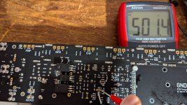
TP107 – 108 registers 2.56V (NOT millivolts)
TP101 – 102 is zero. The output transistors are not installed so should be 700-800mV.
I would sincerely appreciate some pointers as to my next move!
Thanks for any help you can offer
The IPS board checks out fine. All the diodes light once above 30V. As suspected the problem is the EF3.
Firstly can I just check I am doing this right please? I have added the extra components as shown on p52 of the build guide. Where it says “D. Next, short the Input shown on the schematic above to ground” - I have taken that to mean running a jumper from the Ctest 1 - Ctest2 link to PSU GND (marked VIN on schematic with Input below it)? Is that right?
Assuming I have got that correct then I can slowly bring the rail voltages up to +50V and -50V without the 200mA fuses blowing, but it doesn’t look good. The rail voltages are corect and the LEDs light equally.
TP107 – 108 registers 2.56V (NOT millivolts)
TP101 – 102 is zero. The output transistors are not installed so should be 700-800mV.
I would sincerely appreciate some pointers as to my next move!
Thanks for any help you can offer
Ground is G1 so you can short the input shown on the schematic to G1. No need to connect it to the PSU ground or G0 but it's ok if you did.Next, short the Input shown on the schematic above to ground”
Are you sure R109 is at maximum ~500 ohms resistance. Please check by measuring between pin 1 and pin 2 for R109 shown on the silkscreen on the underside of the board.TP107 – 108 registers 2.56V (NOT millivolts)
If the outputs aren't installed then measuring between TP101 - 102 will be Zero. That's why we are taking the measurement between TP107 - 108TP101 – 102 is zero. The output transistors are not installed so should be 700-800mV.
YesIs 2x20000uF in the psu with 59v enough for a stereo pair of boards?
Stuart, thanks for the reply. Glad I got the extra layout right. Yes, I have checked R109, pins 1 and 2 on the underside many times. 500 ohms. Understand now re TP101-102.Are you sure R109 is at maximum ~500 ohms resistance. Please check by measuring between pin 1 and pin 2 for R109 shown on the silkscreen on the underside of the board
The 200mA fuses blow if I turn on at 50V without current limiting...
@stuartmp Hi Stuart. These are the results with 50V+/- into board wired for 71V. DMM- on G1. D105A cathode 2.3V; D106A anode -0,84VPlease check each of those nets to G1 and report back the voltage.
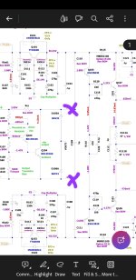
It looks like there could be a problem with one of the components in the vba multiplier area as both values should be fairly close to each other except one is positive and the other negative.These are the results with 50V+/- into board wired for 71V. DMM- on G1. D105A cathode 2.3V; D106A anode -0,84V
Give that you have advised that the ips board was functioning correctly please inspect the following area. Please check all components are correctly installed with the correct values. Check Q103 is not shorted in any way to the heatsink.
Attachments
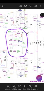
@stuartmp Hi Stuart, I thoroughly checked everything before my initial post but have gone back and reviewed again. All the resistors in the area specified match the BOM (in fact ALL the resistors are correct). All diodes correctly oriented, all appear functioning normally. D105A,106A read approx 1.4 on reversed polarity rather than OL. There are no shorts to ground from any of the transistor legs. I have checked all the transistor values again using DMM diode function. Excxel spreadsheet enclosed with results compared with the functioning board. These are checked in circuit. I recognise I may need to start removing components to check off-board. You can see why I am stuck - doesn't appear to be any obvious problem! Really appreciate your help. Photos as per earlier postGive that you have advised that the ips board was functioning correctly please inspect the following area. Please check all components are correctly installed with the correct values. Check Q103 is not shorted in any way to the heatsink.
Attachments
Hey all, I just completed all of my testing of the boards without the output transistors. Quick question, for test G (Q101, Q102) I get slightly less than 1.5v. I'm getting 1.45v and the reading slowly decreases, not holding steady.
Is this expected behavior? I'm using the TTC and TTA transistors.
Any help greatly appreciated, thanks.
Is this expected behavior? I'm using the TTC and TTA transistors.
Any help greatly appreciated, thanks.
@stuartmp well if I was baffled before, I am even more so now. The 2 boards combined had failed using the Cobra-S2 - the fuses blew promptly. So I bought a bench supply, and the the IPS board in isolation seemed OK. EF3 appeared faulty. But, with the power being brought up gradually to 51V, the current never reached 0.5A and the fuses didn't blow. So, since previous post (4877), I thought I would combine the boards again and test them together with the bench supply, bringing the voltage up gradually. Astonishingly everything appears to function properly. All LEDs illuminated. Bias voltage TP107-108 880mV. R11 adjusted for 5V at TP1-2. TP3-TP4 601mV. TP105 to +ve rail 1.6. TP106 to -ve rail -1.702. R25 adjusted DC offest to zero. D105A cathode to GND 1.933V, D106A anode to GND, -1.927.
Completely at a loss here but...everything seems to be working. Next step I guess is to reconnect the Cobra and see what happens .
Completely at a loss here but...everything seems to be working. Next step I guess is to reconnect the Cobra and see what happens .
All working fine with Cobra and 71v. 0.5A fuses intact. Everything measures good - only anomaly is TP105 to rail is 1.721, TP106 to rail is -1.858. I will install the outputs and proceed. Thanks to everyone for help, @mainframe99 and @stuartmp
- Home
- Amplifiers
- Solid State
- DIY Class A/B Amp The "Wolverine" build thread