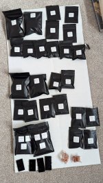
Wilfredo HiFi and DIYA Tribble looking at the boards and bags for his (?) next project, a Wolverine EF3-3. We discussed it and originally thought we'd buy the heatsinks from @fireanimal, he also offered components. We were going to buy the actives too, but having thought about it for a while we decided to push the boat out and buy the complete component set. This is the result. Securely packed, promptly delivered. The component leads come pre bent 😱. Wilfredo and I disagree on this. He (?) thinks it's a nice touch, I'm more ambivalent, I can't help feeling that if Nero had done DIYA he'd have had his leads pre-bent too...
Despite Wilfredo's enthusiasm, construction will not begin until soft start, PSU and speaker protection boards are complete and tested.

Despite Wilfredo's enthusiasm, construction will not begin until soft start, PSU and speaker protection boards are complete and tested.

Most likely 625VA, dual bridge, 6x15mF Panasonic caps. 800-900VA would be better but 625VA is the largest toroid I have.@janusz What size transformer (VA) are you going to use with the Sanken 2SA2223A/2SC6145A ?
I was looking at a 900VA @45v transformer then onto an LT4320 PSU board with 4 x KEMET ALC70C153EL100 15000 µF caps.
In may current build I use 1kVA toroids each feeding one EF3-3 board for frequencies over 400Hz, while the 100-500Hz range will be covered by Silicon Chip 500W amp. Actually mine will be about 430W. As voltages are +/-71V I'm using MG transistors with EF3-3. I'm building two such units each for one channel, while active sub handles frequencies below 100Hz.
EF3-4 will be stand alone unit. Or I'll use it for lower frequencies 100-700Hz, while I'll use Stochino amp for over 700Hz. I have a nice three way semi active system based on 18sound 2x6.5", 5" Audax midrange and Morel tweeter. Mid to high crossover is first order passive. Low to mid is active. Below 100Hz is an active sub.
I appreciate the photo of the underside of the IPS board. But I noticed that you did not install the J1 jumper wire as instructed on page 11 of the build guide. Makes me wonder if I missed something. Thanks for any clarification.Hello all,
Sorry for these questions, but got a little bit of an issue with building the boards.
I had some issues with power (using bench power supply ) on the IPS board (ver 3.8) , I think after setting the bias the - and + got messed up on the breadboard and since then whenever I have negative voltage the LED's D10 and D11 light up, but as soon as I give the board + power D12 and D3 come on but immediately D10 and D11 shut off. I had to replace Q12 and Q14 since they were shorted emitter to collector , as well as changing C3 since the cap was only reading 6uF instead of 10uF. The board still measures 5V across TP1 to TP2 even when the transistors were bad.
Everything else looks ok as far as I can tell, and the led's looked ok before when I put it onto the bread board previously. Just had a couple cooks in the kitchen and got things messed up a bit. The picture is with both the + and - voltage at 25 V and .005 amps.
Also, on my second set of boards (IPS 3.8 and EF-3-4 V4.0) I have tried to check the output (using signal generator at 1kHz and 100mVpp and when ever I put the ground on the speaker output the sine wave goes flat. I did not see anything wrong, and I did not want to try it with the output mosfets since the sine waves are so weird. Not smooth but kind , almost sawtooth. I did set the resistance on the POT on R109 to 485 ohms since it would not go up to 500ohms
but yet still getting full voltage (voltage that is from the power supply) between R111A and R111B
The oscilloscope image is of the board without the ground of the oscilloscope attached to anything as it just goes flat.
Sorry, for being long winded and not sure if I have explained enough.
But appreciate any insight. Thanks!!!!View attachment 1307325View attachment 1307326View attachment 1307327View attachment 1307328View attachment 1307329View attachment 1307330
I am an almost-newbie here, having built a couple of ACA kits, with great results. I purchased the EF3-4 boards, and was quite daunted by the prospect of sourcing all the components. Approached @fireanimal for the heatsinks and was delighted to accept offer of heatsinks + components. Great communication re available options, very helpful, and all arrived very nicely and securely packaged. Thanks!
Attachments
For me it was the time it takes and the angsty stuff about choice of active devices. It can take a long time before it's all done and dusted & I really don't enjoy the process at all. I decided to ignore my urge to hair shirt it and got the lot from @fireanimaland was quite daunted by the prospect of sourcing all the components
I had no idea that parts were even available in little baggies, I may have gone that route, but probably not since I already have so much.
I’m hoping to get some answers for some questions I have about this. I’m getting ready to start the project and it looks like my boards are from the second group buy. What is the differences between the boards, stability? I see that between the second and fourth group buy that the schematic shows some extra capacitance. For example, in the fourth there is C125 and C126 which aren’t on the second. They are just wired in parallel with C123 and C124. Is that a change that should be made? Should the capacitance be raised from 270uF to 560uF? Would essentially be the same as adding those two extra capacitors in the most updated board. I don’t want to show too much of the schematic, but this is what I am talking about.


I’m just wondering what the differences are between the versions. I’m sure it’s somewhere in this thread, but that’s a lot of reading lol.
I’m sure it’s been asked, but what are the downsides if you were to you say higher voltage? All the devices in the circuit are rated for that voltage, example it says for 71v rail you want a transformer that is 50-0-50. What if I happen to have some transformers that are 60-0–60? Or slightly higher? Increasing the rails to a +/- 80v, 85v would increase output power, I’m just curious why they are limiting it to 71 V
Lastly, I have a question about output transistors. I was wondering about the benefits of going from six outputs to eight outputs and the exact devices being used. it looks like the answered to that is basically the amplifiers ability to drive loads. I have the 8 device versions, I have many, many NJW0302/0281 and NJW1302/3281. These would work well, but probably not the best choices for loads that are going to be lower impedance. So while I don’t have as many I do have plenty of MJL1302/3281 and MJL4302/4281. While the latter is a more robust device, it would seem according to the list that both are going to be capable in driving lower loads and should be fairly equal in this build. Unless of course, you like the fact that they are more robust and have a slightly faster Ft of 35 MHz vs 30 MHz.
I am just curious what you all feel are going to be the best outputs to use. I want these amplifiers to be as clean as possible, but at the same time, extremely robust and capable of driving demanding loads. Once I hear back on the rail voltage question, whether or not it’s OK to go a bit higher, I will make a decision on the transformers. I have a few to choose from, but I’m thinking I would like to go with a single 800VA transformer per channel. Im building 4 channels so 4 transformers in total.
I am sure I will have more questions in the future as I go along, but thought this would be a good starting point.
Thank you all,
Dan
I’m hoping to get some answers for some questions I have about this. I’m getting ready to start the project and it looks like my boards are from the second group buy. What is the differences between the boards, stability? I see that between the second and fourth group buy that the schematic shows some extra capacitance. For example, in the fourth there is C125 and C126 which aren’t on the second. They are just wired in parallel with C123 and C124. Is that a change that should be made? Should the capacitance be raised from 270uF to 560uF? Would essentially be the same as adding those two extra capacitors in the most updated board. I don’t want to show too much of the schematic, but this is what I am talking about.
I’m just wondering what the differences are between the versions. I’m sure it’s somewhere in this thread, but that’s a lot of reading lol.
I’m sure it’s been asked, but what are the downsides if you were to you say higher voltage? All the devices in the circuit are rated for that voltage, example it says for 71v rail you want a transformer that is 50-0-50. What if I happen to have some transformers that are 60-0–60? Or slightly higher? Increasing the rails to a +/- 80v, 85v would increase output power, I’m just curious why they are limiting it to 71 V
Lastly, I have a question about output transistors. I was wondering about the benefits of going from six outputs to eight outputs and the exact devices being used. it looks like the answered to that is basically the amplifiers ability to drive loads. I have the 8 device versions, I have many, many NJW0302/0281 and NJW1302/3281. These would work well, but probably not the best choices for loads that are going to be lower impedance. So while I don’t have as many I do have plenty of MJL1302/3281 and MJL4302/4281. While the latter is a more robust device, it would seem according to the list that both are going to be capable in driving lower loads and should be fairly equal in this build. Unless of course, you like the fact that they are more robust and have a slightly faster Ft of 35 MHz vs 30 MHz.
I am just curious what you all feel are going to be the best outputs to use. I want these amplifiers to be as clean as possible, but at the same time, extremely robust and capable of driving demanding loads. Once I hear back on the rail voltage question, whether or not it’s OK to go a bit higher, I will make a decision on the transformers. I have a few to choose from, but I’m thinking I would like to go with a single 800VA transformer per channel. Im building 4 channels so 4 transformers in total.
I am sure I will have more questions in the future as I go along, but thought this would be a good starting point.
Thank you all,
Dan
Don't worry about adding C125/126 for 1st/2nd GB. Won't make a difference.
50V TX secondaries (either 50-0-50 or 2x50 or 4x50 depending on your PSU arrangement) are the highest you can go unless you want to turn the entire amp into a fuse.
The amp is clean by design. If you use 800VA tx's per board the rails will be stiff, use MJE15032/33 or 15034/35 drivers and MJL4281/4302 outputs or MT200 sanken outputs as per sheet 2 of the BOM. Make sure to use the right complimentary compensation capacitance in the IPS.
Thank you for the answers. What do you mean exactly by turning the amplifier into a fuse? With higher rails, it would blow???Don't worry about adding C125/126 for 1st/2nd GB. Won't make a difference.
50V TX secondaries (either 50-0-50 or 2x50 or 4x50 depending on your PSU arrangement) are the highest you can go unless you want to turn the entire amp into a fuse.
The amp is clean by design. If you use 800VA tx's per board the rails will be stiff, use MJE15032/33 or 15034/35 drivers and MJL4281/4302 outputs or MT200 sanken outputs as per sheet 2 of the BOM. Make sure to use the right complimentary compensation capacitance in the IPS.
You say if I use 800VA transformers for each channel my will be stiff, what do you mean by that? Do you mean they’ll be stable and there won’t be much sagging? I would figure that the more capable, the transformer, the better, as far as current abilities. On the list, it says that 1200VA for both channels is overbuilt or whatever word they used. I see that a lot of people used to transformers per amplifier, to make them a dual mono design, I would want to do the same, so I figured a robust transformer would be a benefit. Am I thinking correctly?
Very good, I’ll use the MJL4281/4302 if they’re going to be the best option for my plan.
Dan
"Fuse" was satire. You will damage something for sure with higher than 70VDC rails. One would safely assume the design around 70VDC rails (50VAC Tx Secondaries) is also incorporating some mains or rail sag fluctuations. So while you think the parts can take more voltage, the max rails are deliberately nominated as such in order to allow for headroom from outside influences and rail sag from high current draw. Running higher rails will mean you don't have any current headroom and then something will turn into a party popper. How much do you like your speakers? Unless your an experienced builder, don't wander from the BOM. Look at the parts on there, these guys have put in some serious hours into this design 👏
You didn't specify what speakers you are designing the amp for. Some builders are targeting a speaker. That gives them a more narrow scope to choose the correct transformer/drivers/outputs. No problem either way, but if you don't know what speakers you're going to use or you think they might change or just want to design for a wide range of applications, then best to go for more robust parts, if within your budget.
Also, 800VA per channel isn't required (as per the transformer chart in the BOM) but because you said you want to go there, what I meant by stiff is the rails will sag less under higher loads. Because of that and the fact you didn't specify a target load (speaker), you should pick the most robust parts from the BOM if your budget or parts stash allows it. You already have 4281's 4302's - they are chonky expensive outputs. Hope you got them from a reputable source, they shouldn't let you down. What driver transistors do you have? If none, your only option is really the MJE series.
In my opinion pretty much all of the outputs and drivers would be fine for 99% of commercial speakers available today at normal listening levels 80-90dB at 3m/10ft listening position. I have built both a 54VDC rail NJW0302/0281 output EF3-3 and a 70VDC MT200 output EF3-4 version wolverine, powering 85dB sensitive 3 way speakers at those levels for hours no issues.
PS: Don't always look at the datasheet schedule for parts (e.g. fT), learn to read the graphs instead. I see a lot of people use the 1943/5200 combo in amp designs here, but to me they look they least desirable choice, and the ones I got from mouser measure poorly (disclaimer I don't own curve tracers - yet)
Happy building. Follow the build guide. Stick to the BOM.
I am stuck in a bit of a loop.
I have pretty much finished my boards; I have tried to make the best component choices possible and matched all essential devices.
I have 65v voltage rails, and I am using the 2SC3503 and 2SA1381 as Pre-drivers. The output devices will be MJL4281/MJL4302.
I have some matched MJE15032 & MJE15033 because I could get them. However, Stuart kindly sold me some 2SC4793 and 2SA1837, which I would like to use.
However, I currently use Monitor Audio PL200, which has 90db 4 Ohm speakers, and overall, I am concerned I might be pushing the 2SC4793 and 2SA1837 too hard.
Any advice on which driver I should go for here?
I absolutely get that some serious hours were put into this amp design from folks light years ahead of me as far as knowledge goes, I’m just simply asking questions. Curious why it was capped at 71v when I have amplifiers running rails with similar components (not design necessarily) with much higher rails. I went to my local electronics store and they have some transformers that are 51-0-51, I’m guessing that extra volt won’t be a problem? But headroom is a good answer."Fuse" was satire. You will damage something for sure with higher than 70VDC rails. One would safely assume the design around 70VDC rails (50VAC Tx Secondaries) is also incorporating some mains or rail sag fluctuations. So while you think the parts can take more voltage, the max rails are deliberately nominated as such in order to allow for headroom from outside influences and rail sag from high current draw. Running higher rails will mean you don't have any current headroom and then something will turn into a party popper. How much do you like your speakers? Unless your an experienced builder, don't wander from the BOM. Look at the parts on there, these guys have put in some serious hours into this design 👏
You didn't specify what speakers you are designing the amp for. Some builders are targeting a speaker. That gives them a more narrow scope to choose the correct transformer/drivers/outputs. No problem either way, but if you don't know what speakers you're going to use or you think they might change or just want to design for a wide range of applications, then best to go for more robust parts, if within your budget.
Also, 800VA per channel isn't required (as per the transformer chart in the BOM) but because you said you want to go there, what I meant by stiff is the rails will sag less under higher loads. Because of that and the fact you didn't specify a target load (speaker), you should pick the most robust parts from the BOM if your budget or parts stash allows it. You already have 4281's 4302's - they are chonky expensive outputs. Hope you got them from a reputable source, they shouldn't let you down. What driver transistors do you have? If none, your only option is really the MJE series.
In my opinion pretty much all of the outputs and drivers would be fine for 99% of commercial speakers available today at normal listening levels 80-90dB at 3m/10ft listening position. I have built both a 54VDC rail NJW0302/0281 output EF3-3 and a 70VDC MT200 output EF3-4 version wolverine, powering 85dB sensitive 3 way speakers at those levels for hours no issues.
PS: Don't always look at the datasheet schedule for parts (e.g. fT), learn to read the graphs instead. I see a lot of people use the 1943/5200 combo in amp designs here, but to me they look they least desirable choice, and the ones I got from mouser measure poorly (disclaimer I don't own curve tracers - yet)
Happy building. Follow the build guide. Stick to the BOM.
I don’t have a target set of speakers. I want to use these with, I’m hoping to use them with many different speakers. I’m building four channels in total because I have a pair of JBL XPL200As that I run with JBL’s DX-1 active crossover and it requires 4 channels of amplification. I also have a few other vintage speakers, JBL L300, ADS L1590, JBL L7, Magnepan 2.7i, ESS AMT-1B. And then I have some diy speakers that I like to listen to a lot. A small two way using a 5.5 inch SS Revelator and Hiquphon tweeter, a large four way using a JBL Sub1500 15” woofer, JBL J251 10” midbass, JBL 435be 3” beryllium compression mid on a H9800 horn, and JBL 045be 1” beryllium tweeter, also with a small horn/waveguide. This last pair require four channels of amplification as well. They can provide a lot of detail as well as the XPL200As which is why I want to build these, plus it’s fun.
The reason I was asking about the outputs is because I simply just do not know. As you mention the 4281/4302 robust and chonky outputs, so I was wondering if maybe some of the less robust parts may be considered better, sonically. If all else is equal beside robustness, then yeah I will go with those. I picked them up from Mouser. I like to outputs to my parts orders periodically so I can build up and they seem to be out of stock frequently. It looks like I’ll need 16 PNP and 16 NPN. I currently have 37 of each, I’ll add 10 of each to my next order since they’re in stock, I like to match my parts as closely as possible. I figured that’s what you meant by stiffness. With less sag theoretically I should get more peak power correct? I know we are talking number that really don’t make a difference. Nobody could discern a 240w amp from a 260w obviously.
For Semis I’ll be using BC550/560C, KSA992/KSC1845, I have TTA004b/TTC004b and KSA1381/KSC3503 (and KSA1220/KSC2690) and will use whichever people consider to be the better part, hopefully someone has an option. On a side note I also have many 2SA1540E/2SC3955E and 2SA1209S/2SC2911S which are higher gain and have a lower cob which I read was better for drivers and predrivers.
For drivers I certainly do have MJE15032/33 and as another member asked about I also have 2SA1837/2SC4793, but if these aren’t robust enough…. Plus I’m wondering from the BOM. I know many of the parts were selected because they are actually available. There were many parts made that are superior, but sadly long gone.
The reason I want these to be as robust as possible is because I want to run pretty much anything I want to them. If I wanted to run a pair of Infinity Kappa 9.1 I would hope I could. They have areas of frequency where they dip to about 1 ohm. Not saying I will run them, but I don’t want to run into a situation where I have to question if it’s a good idea to run the speakers.
The two amplifiers you made, which one is your preferred? Thank you for your time!
Dan
I would use the Sanken C4883A / A1859A in your situation, those toshiba's will be right at the limit. I have some if you cant find elsewhere. Next choice would be the MJE drivers, but that would require you installing the higher value comp caps.
The C4883A/A1859A would be a better set of drivers than the MJE parts in this amplifier? I figure I’m only going to build these once so I might as well put the best parts possible into them if they’re available. I know parts with higher Ft are more desirable, but would love to hear your thoughts.
Dan.
Pretty sure 50V secondaries are the max , 51V could be okay but might pay to check with one of the design team.
No sonic differences between my current 3 pair and 4 pair.
Discontinued 4883A/1859A have a very nice spec sheet, used in all my builds and I believe fireanimals but some old guard here like the very obsolete 4793/1837 combo but these aren't as robust. I'm not recommending the Sankens though as they are no longer available anywhere other than DIYaudio members, why I said go the MJE series. Don't think you could measure or hear a difference between the drivers.
I appreciate that, I reached out to fireanimals and he is going to help me out with the 4883/1859 pairs and also said he has many other parts for this build if I am in need, super nice. I sent him my home address name and phone number, just waiting to hear back. Probably just checking to make sure that I paid and to be a part of this build.Pretty sure 50V secondaries are the max , 51V could be okay but might pay to check with one of the design team.
No sonic differences between my current 3 pair and 4 pair.
Discontinued 4883A/1859A have a very nice spec sheet, used in all my builds and I believe fireanimals but some old guard here like the very obsolete 4793/1837 combo but these aren't as robust. I'm not recommending the Sankens though as they are no longer available anywhere other than DIYaudio members, why I said go the MJE series. Don't think you could measure or hear a difference between the drivers.
Out of curiosity, has anyone asked about the 2SC5171 and 2SA1930? I have a bunch of them and their specs look to be pretty much identical to the 4883/1859 pair except having a higher Ft (120 MHz vs 200 MHz) and slightly lower Veb.
Feel free to tell me to stay in my lane, but I thought I might as well ask. I know these drivers with higher Ft are often sought after as they are no longer made and make better drivers. I actually have successfully replaced several 2SC1913/2SA913 pair with KSC2690/KSA1220 as drivers to keep the higher transitional frequency. Smaller package, but rated for higher dissipation and current.
Anyways, thoughts? Or just stick with the 120 MHz devices?
Dan
- Home
- Amplifiers
- Solid State
- DIY Class A/B Amp The "Wolverine" build thread