Hi Janusz,One technical question: what are the rules when choosing NFB resistors for a given gain. Here these are 27k and 1k and gain is 28. I have active systems and would like all my amps have the same gain so I could switch them. So what about 13k and 470 ohm or 27k and 820 ohm or 13k and 390 ohm. Apartt from thermal noise what is the difference in running this amp (or any amp) with these different nfb resistor values? What are the rules?
Thanks,
Are you able to match levels in the active system at the line level because that could be preferable.
- Dan
There are several things going on with the choice of feedback resistors and input impedance. Input impedance is approx. equal to R2||R0. Bias current for the input transistors comes through R2 and R21A/B, so for DC offset reduction R21A + R21B = R2 and Hfe Q1=Q2 and VbeQ1=Q2. This ensures that the bias current drawn by the input pair is equal and through equal resistors, making the base voltages equal. AC gain is now determined by the feedback voltage divider R9 and R21A+B and the input divider R00+R1+R0||R2. To a first approximation we can ignore R00 and R0, and simplify the gain equation:
Vout (R9/(R21A+B+R9) = R2/(R1+R2)Vin. Vout/Vin = [R2/(R1+R2)]/[R9/(R21A+B+R9)]. If R2 = R21A+B and R1 = R9 gives Vout/Vin = (R21A+B)/R9.
If you want to tinker with the gain slightly, small adjustments in the value of R9 would be your best bet. You can try parallel combinations or buy some E96 series resistors around the value of R9 from the BOM. Basically, you are adjusting the feedback network to compensate for the 1% tolerances of resistors. While any set of resistors that gives the desired gain ratio can be used, straying far from the match between R2 and R21AB will induce DC offset issues, although this circuit has a DC balance adjustment. The match between R1 and R9 is less critical. An alternative is to use a 4-wire ohm meter and measure a bunch of resistors until you find ones that are very close in value. I did that with a batch of 5% emitter resistors and got all of the parallel pairs for each emitter within 100 uohms, which comes out to +/- .02%
If you are driving from the outputs of active crossovers, you can probably use 10k input impedance rather than 22k, thereby lowering the noise from the resistors, but if you go too low, C1 becomes a problem unless you want to go to an electrolytic. That would likely introduce some distortion.

Thank you very much mhuth1776 for your explanation.
However could you clarify what is B and R21A and R21B? Is R21 = R21A + R21B?
Thank you,
cheers,
However could you clarify what is B and R21A and R21B? Is R21 = R21A + R21B?
Thank you,
cheers,
Correct - there are two series resistors for the feedback, either to get the correct value or to minimize tolerance and thermal drift. It might also reduce noise, but I'm less certain about that. The schematic makes it quite clear.
I tried to use a bit of shorthand for those resistors and apologize if I've caused confusion. Anytime you see R21... it is the series resistance of the two separate resistors that matters.
I tried to use a bit of shorthand for those resistors and apologize if I've caused confusion. Anytime you see R21... it is the series resistance of the two separate resistors that matters.
So very informative to completely read this whole thread !!! Fireanimal's fancy test equipment and measurements
answered a few questions regarding layout and component choices. GREAT reading material while designing my little EF3.
The grounding layout test was very valuable.
I just don't have the $ or the room for big amps , but no reason why I can't have Wolverine type performance. Or even better PSRR.
I only have a 300VA toroid , 4 X 6800uf caps, and a single 25A bridge on hand. I had to make a smaller OPS.
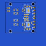
A spinoff of my designs is the fact there will be 3 new SMD IPS's soon. All compatible with any of these OPS's ....
I just loved to see all the joy of everyone's fanaticism in building these Wolverines. I even changed some things in my designs going by what I
read here (10K + 390R FB+input Z).
PS - reliability of this design is measured in decades , I'm listening to the 40 year old Wolverine OPS (my HK680 integrated amp).
OS
answered a few questions regarding layout and component choices. GREAT reading material while designing my little EF3.
The grounding layout test was very valuable.
I just don't have the $ or the room for big amps , but no reason why I can't have Wolverine type performance. Or even better PSRR.
I only have a 300VA toroid , 4 X 6800uf caps, and a single 25A bridge on hand. I had to make a smaller OPS.
A spinoff of my designs is the fact there will be 3 new SMD IPS's soon. All compatible with any of these OPS's ....
I just loved to see all the joy of everyone's fanaticism in building these Wolverines. I even changed some things in my designs going by what I
read here (10K + 390R FB+input Z).
PS - reliability of this design is measured in decades , I'm listening to the 40 year old Wolverine OPS (my HK680 integrated amp).
OS
Attachments
Looking good OS, I like the plan for SMD and the smaller boards may work well for surrounds or Atmos channels 👍🏻 in a multichannel build
Yes , the PSRR is more important to me. Running many channels off the same supply.
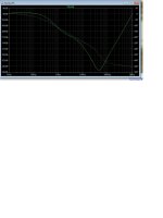
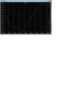
Notice ( below 1) where the most cancellation is at 40-70Khz. This design was made for SMPS's.
I saw your test of the Wolverine and the switching peaks at 50 + 70khz. CFA (below 2) does the best in the bass realm.
OS
Notice ( below 1) where the most cancellation is at 40-70Khz. This design was made for SMPS's.
I saw your test of the Wolverine and the switching peaks at 50 + 70khz. CFA (below 2) does the best in the bass realm.
OS
Attachments
Hi OS, please ensure that you enter the ESR into all of the capacitors in your simulation otherwise your simulated PSRR maybe out.the PSRR is more important to me
Oh , yeah . Wolverine PSRR is pretty good. Needs those real big ripple filter caps. But it is not a symmetrical design , less bass
and HF cancellation. Most builders use huge separate filters or even dual mono - should be good .
If you regulate the cascode and LTP CSS on the Wolverine , it can approach -110db - 20hz to 100khz.
and HF cancellation. Most builders use huge separate filters or even dual mono - should be good .
If you regulate the cascode and LTP CSS on the Wolverine , it can approach -110db - 20hz to 100khz.
Attachments
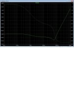
ESR and serial resistance is added. You can also simulate the phase differential of the ripple source.Hi OS, please ensure that you enter the ESR into all of the capacitors in your simulation otherwise your simulated PSRR maybe out.
If you read the Cordell and Self amplifer books , they admit a single ended VAS (CCS) based design has a slight PSRR "hit".
It is what it is !! That's why you don't run multiple Wolverines off the same PS.
The positive is that the Wolverine has obscenely low THD 1K - 20K.
At 20Hz , the symmetrical designs rule. Even in THD - at high powers.
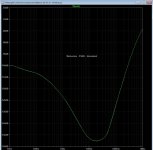
see the PSRR at around 1K , that is why Fireanimal can get -150db THD.
OS
Last edited:
This is the Wolverine PSRR using our simulation model.Wolverine PSRR
Attachments
Hello Gents,
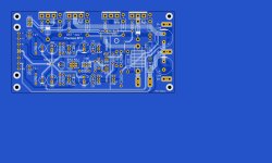
Did a lot of reading on wire postioning including the Wolverine docs. I understand most of it but stil have a simple question. Would it be better to route the power cables together with the speaker cables or leave a bit of space (like in the pic) between them?
thx

Did a lot of reading on wire postioning including the Wolverine docs. I understand most of it but stil have a simple question. Would it be better to route the power cables together with the speaker cables or leave a bit of space (like in the pic) between them?
thx
This is the way I did it based on a suggestion from Stuart.
It has worked very well for me in terms of keeping higher current leads away from the sensitive feedback path and input leads.

It has worked very well for me in terms of keeping higher current leads away from the sensitive feedback path and input leads.
Thx...will route them the same.keeping higher current leads away from the sensitive feedback path
w.
We have scrutinized the original bias spreader implementation, and completely overhauled it. After many implementations and bench testing various combinations of resistors and transistors, both the EF3-3 and the EF3-4 have been reworked and new modifications / values available. The modifications are easy and straight forward.
During the re-design it was decided that the original MJE340G was no longer going to be used, due to the fact they are not binned and there is too wide of a gain margin in those parts, resulting in too many values for RCC and potential mismatch and non-linearity if the wrong value for RCC was chosen.
The new transistors for both Q103 and Q104 are readily available, and tightly binned. Q103 and Q104 are swapping duties in the process, which allowed for way better tracking of both the heatsink and ambient temperatures. Q104 is now mounted on the PCB, and Q103 on the EF3-3 is mounted via lead wires to the heatsink holes beside the output transistors. On the EF3-4 it will be mounted under the PCB between the drivers on the main heatsink.
Testing was done with different combinations of drivers and outputs, while bias and heatsink temperature were monitored and logged in real time. We used both static and dynamic testing to confirm the results and that we had no thermal runaway, but the bias was also not dropping below a comfortable level. We were aiming for close to 0 but slightly negative bias vs temperature response, which was achieved on both the EF3-3 and EF3-4. The static test was 200 watts RMS into 4 ohms, and the dynamic test was a short playlist plated at maximum level into 4 ohms.
These results and the final outcome were not something that could be solved with simulation easily, and only with bench testing and real world results, could we fine tune the simulation and calculations to provide accurate and repeatable results.

Left Y axis is mV and the Right Y axis is heatsink temp °C. Bias drops between tracks and transitions during the songs. With the bias dropping as low as 8mV.


Left and Right Y Axis are now scaled the same in the above image and both correspond to both mV and °C. There is a substantial improvement, even with the heatsink temperature exceeding 60°C.


We can see again a great result with the modifications on the EF3-4, with the bias holding up during all transitions.
I want to reiterate, these tests were done at full level into 4 ohms, and way beyond a level that would normally be played at, I calculated SPL at 10ft would be 110-112 dB with peaks around 125 dB.
Here is the EF3-4 played at a more normal level into 8 ohms. SPL would be 95dB with 105-108dB peaks at 10 ft.

Basically no change in bias or heatsink temperature at these listening levels.

Here Q104 was heated to verify its response to temperature, as you can see when heated enough, it will fully shutdown the bias.

EF3-3 with Q104 mounted on the PCB and Q103 on the heatsink with flywire leads.
R106 - 1.6k
R107 - 1.4k
R108 - 560r
R109 - 500ohm Trimmer
RCC - 56r
Q103,Q104 - BD13516S(TU) | BD13716S(TU) | BD13916S(TU) ONLY FULLY ENCAPSULATED VERSIONS
R106 - 3.9k
R107 - 1.5k
R108 - 560r
R109 - 500ohm Trimmer
RCC - 47r
Q103,Q104 - BD13516S(TU) | BD13716S(TU) | BD13916S(TU) ONLY FULLY ENCAPSULATED VERSIONS
Part #'s to follow for those who need them.
During the re-design it was decided that the original MJE340G was no longer going to be used, due to the fact they are not binned and there is too wide of a gain margin in those parts, resulting in too many values for RCC and potential mismatch and non-linearity if the wrong value for RCC was chosen.
The new transistors for both Q103 and Q104 are readily available, and tightly binned. Q103 and Q104 are swapping duties in the process, which allowed for way better tracking of both the heatsink and ambient temperatures. Q104 is now mounted on the PCB, and Q103 on the EF3-3 is mounted via lead wires to the heatsink holes beside the output transistors. On the EF3-4 it will be mounted under the PCB between the drivers on the main heatsink.
Testing was done with different combinations of drivers and outputs, while bias and heatsink temperature were monitored and logged in real time. We used both static and dynamic testing to confirm the results and that we had no thermal runaway, but the bias was also not dropping below a comfortable level. We were aiming for close to 0 but slightly negative bias vs temperature response, which was achieved on both the EF3-3 and EF3-4. The static test was 200 watts RMS into 4 ohms, and the dynamic test was a short playlist plated at maximum level into 4 ohms.
These results and the final outcome were not something that could be solved with simulation easily, and only with bench testing and real world results, could we fine tune the simulation and calculations to provide accurate and repeatable results.
EF3-3 Original -3.25mV/°C
Left Y axis is mV and the Right Y axis is heatsink temp °C. Bias drops between tracks and transitions during the songs. With the bias dropping as low as 8mV.
EF3-3 After -0.068 mV/°C
Left and Right Y Axis are now scaled the same in the above image and both correspond to both mV and °C. There is a substantial improvement, even with the heatsink temperature exceeding 60°C.
EF3-4 Original -2.415 mV/°C
EF3-4 After -0.155 mV/°C
We can see again a great result with the modifications on the EF3-4, with the bias holding up during all transitions.
I want to reiterate, these tests were done at full level into 4 ohms, and way beyond a level that would normally be played at, I calculated SPL at 10ft would be 110-112 dB with peaks around 125 dB.
Here is the EF3-4 played at a more normal level into 8 ohms. SPL would be 95dB with 105-108dB peaks at 10 ft.
Basically no change in bias or heatsink temperature at these listening levels.
Q104 Response
Here Q104 was heated to verify its response to temperature, as you can see when heated enough, it will fully shutdown the bias.
EF3-3 with Q104 mounted on the PCB and Q103 on the heatsink with flywire leads.
EF3-3 VALUES
R105 - 2kR106 - 1.6k
R107 - 1.4k
R108 - 560r
R109 - 500ohm Trimmer
RCC - 56r
Q103,Q104 - BD13516S(TU) | BD13716S(TU) | BD13916S(TU) ONLY FULLY ENCAPSULATED VERSIONS
EF3-4 VALUES
R105 - 1.4kR106 - 3.9k
R107 - 1.5k
R108 - 560r
R109 - 500ohm Trimmer
RCC - 47r
Q103,Q104 - BD13516S(TU) | BD13716S(TU) | BD13916S(TU) ONLY FULLY ENCAPSULATED VERSIONS
Part #'s to follow for those who need them.
fireanimal - That is a good improvement. The original thermal overcompensation was not the greatest design choice, IMO. It is better to be slightly undercompensated to preclude the possibility of the bias collapsing.
Ed
Ed
Hi Guy's,
I'd just like to add a small addition to @fireanimal comments. As I'm sure you can all see from the results above a significant amount of time was dedicated to compiling these test results. I would just like to personally thank @fireanimal for his dedication to this project. While @jjs and I were running simulations and discussing component choices with the other Wolverine team members. @fireanimal was actually taking the EF3-X's PCB's on and off the heatsink, de soldering, re soldering, testing and re testing time after time after time. Creating test jigs and incorporating very accurate logging equipment needs to be acknowledged. The simulation results would not have been able to be validated without your testing.
Once again thanks again for your dedication to this project. The Wolverine's performance has certainly improved from your input on this thermal compensation deep dive. 🙏🙏🙏
Just so everyone knows @fireanimal test results were validated by @danieljw. I also personally thank him for his time and dedication to this project.
I hope that everyone finds the modification easy to install.
We will update the bom and build guide over the coming days...
Last edited:
- Home
- Amplifiers
- Solid State
- DIY Class A/B Amp The "Wolverine" build thread