
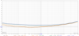
These are great results Andy. Looks like the TTA/TTC are slightly better but they are within 1dB or so.
Nearly ready to start testing….one more Mouser parcel (delayed until later this week) with some bits that I still require. The EF3-4 boards will go into an existing 5U enclosure and the EF3-3 is Planned to be fitted into a box sometime early in the new year.
Attachments
How precise should be L1? My first try following the build guide resulted in 1.1uH@1kHz (I am not able to measure at higher frequencies). Should I add more turns or is it good enough?

I don't know of any other designs that would match that. This was also a full bandwidth sweep to 192kHz so 20k to the 9th harmonic.Lowest distortion design on diya thus far? I mean relative to say 200wpc?
While being a bit off should be ok. If you make it as per the build guide you should be right on the money.How precise should be L1? My first try following the build guide resulted in 1.1uH@1kHz (I am not able to measure at higher frequencies). Should I add more turns or is it good enough?View attachment 1123105
When you measure the inductance you will get a more accurate result with short leads and only the minimum amount of excess wire at the ends of the windings.
I would try two extra coils to start with. Cut the leg length right back and stick the ends straight into your meters sockets if possible.
If your over you can always cut off one coil and re measure
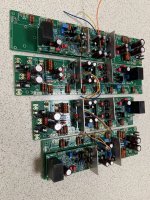
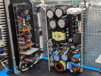
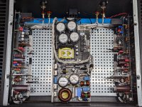
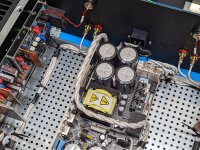
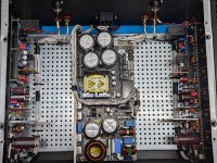
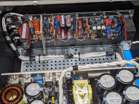
I am getting close to the finish line.. Now it pays out that I have done all the work on the enclosure and the power supply upfront. Due to the lack of a lab power supply I used the PSU. A real kitchen table build..
With the Antek AS-4445 i achieve +/- 62.3V without load. All initial tests and adjustments of both channels went fine. The main reason why is the stunning BOM and Build Guide provided by the Wolverine team - so thanks again!
Now I only have to add the output transistors and go through the final checks and adjustments. Unfortunately I won't have time to solder next days 😭

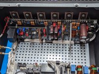
Test Setup on kitchen table workbench.

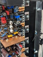
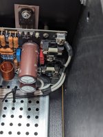
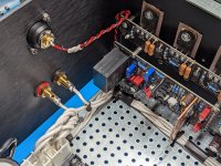
I triple checked the test leads, they are prone to snap away and cause shorts. Unfortunately R111a and R111b are not marked as Test points on the solder mask of the boards I have. That's why the leads of those resistors are a bit short in my build and it's difficult to clamp test clips there.
With the Antek AS-4445 i achieve +/- 62.3V without load. All initial tests and adjustments of both channels went fine. The main reason why is the stunning BOM and Build Guide provided by the Wolverine team - so thanks again!
Now I only have to add the output transistors and go through the final checks and adjustments. Unfortunately I won't have time to solder next days 😭
Test Setup on kitchen table workbench.
I triple checked the test leads, they are prone to snap away and cause shorts. Unfortunately R111a and R111b are not marked as Test points on the solder mask of the boards I have. That's why the leads of those resistors are a bit short in my build and it's difficult to clamp test clips there.
Looks Great, but use the Test Points instead of the resistors it will be easier. TP101 TP102. BTW those resistors were never marked as TP.I am getting close to the finish line.. Now it pays out that I have done all the work on the enclosure and the power supply upfront. Due to the lack of a lab power supply I used the PSU. A real kitchen table build..
With the Antek AS-4445 i achieve +/- 62.3V without load. All initial tests and adjustments of both channels went fine. The main reason why is the stunning BOM and Build Guide provided by the Wolverine team - so thanks again!
Now I only have to add the output transistors and go through the final checks and adjustments. Unfortunately I won't have time to solder next days 😭
View attachment 1123143
Test Setup on kitchen table workbench.
View attachment 1123144
I triple checked the test leads, they are prone to snap away and cause shorts. Unfortunately R111a and R111b are not marked as Test points on the solder mask of the boards I have. That's why the leads of those resistors are a bit short in my build and it's difficult to clamp test clips there.
There is a German saying: "why do it the easy way when you can also do it the hard way?"
Jokes aside, I was just following the instructions in the build guide:

Edit: well the dumbest thing one can do is to follow instructions without thinking 🤔 I just could have followed the traces to see that TP 101 and TP 102 are sufficient for this measurements. Cheers from the kitchen table amp camp 👍
Jokes aside, I was just following the instructions in the build guide:
Edit: well the dumbest thing one can do is to follow instructions without thinking 🤔 I just could have followed the traces to see that TP 101 and TP 102 are sufficient for this measurements. Cheers from the kitchen table amp camp 👍
Last edited:
Hi @AddiDub,I am getting close to the finish line.. Now it pays out that I have done all the work on the enclosure and the power supply upfront. Due to the lack of a lab power supply I used the PSU. A real kitchen table build..
With the Antek AS-4445 i achieve +/- 62.3V without load. All initial tests and adjustments of both channels went fine. The main reason why is the stunning BOM and Build Guide provided by the Wolverine team - so thanks again!
Now I only have to add the output transistors and go through the final checks and adjustments. Unfortunately I won't have time to solder next days 😭
View attachment 1123143
Test Setup on kitchen table workbench.
View attachment 1123144
I triple checked the test leads, they are prone to snap away and cause shorts. Unfortunately R111a and R111b are not marked as Test points on the solder mask of the boards I have. That's why the leads of those resistors are a bit short in my build and it's difficult to clamp test clips there.
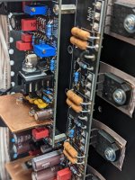
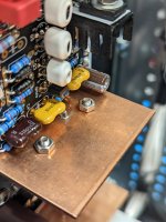
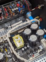
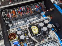
You appear to have plenty of room to play with between edge of pcb, also the O/P trans locations, and the rails holding the heatsinks together. In which case, this would perhaps answer my own question that I posed in post #937 - is that a Dissipante 4/ enclosure? Plenty of room to then fit that bottom plate ...... had I realised, I should have also got the 4/ unit instead of the 3/ it seems! Blast it ...!!!
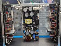
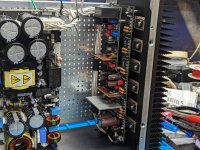
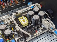
Yes there is lots of room on the 4U chassis, here are some pics of one of my earlier builds.Hi @AddiDub,
You appear to have plenty of room to play with between edge of pcb, also the O/P trans locations, and the rails holding the heatsinks together. In which case, this would perhaps answer my own question that I posed in post #937 - is that a Dissipante 4/ enclosure? Plenty of room to then fit that bottom plate ...... had I realised, I should have also got the 4/ unit instead of the 3/ it seems! Blast it ...!!!
Attachments
-
 PXL_20220717_151808063.jpg615.9 KB · Views: 233
 -
 PXL_20220717_152612881.jpg677.8 KB · Views: 231
 -
 PXL_20220717_152630319.jpg627 KB · Views: 224
 -
 PXL_20220717_152639173.jpg649.9 KB · Views: 441
 -
 PXL_20220717_152706470.jpg466.2 KB · Views: 211
 -
 PXL_20220717_152719404.jpg466.1 KB · Views: 215
 -
 PXL_20220717_152745949.jpg372.4 KB · Views: 206
 -
 PXL_20220718_181429770.jpg727.9 KB · Views: 411
 -
 PXL_20220718_181444974.jpg777.7 KB · Views: 203
 -
 PXL_20220718_181452706.jpg694.4 KB · Views: 199
 -
 PXL_20220718_181501210.jpg433.5 KB · Views: 199
 -
 PXL_20220718_181507127.jpg535.3 KB · Views: 191
 -
 PXL_20220718_181516558.jpg616.7 KB · Views: 193
 -
 PXL_20220718_204941925.jpg745.7 KB · Views: 218
 -
 PXL_20220718_204948885.jpg634.3 KB · Views: 191
 -
 PXL_20220718_205001434.jpg680.3 KB · Views: 189
 -
 PXL_20220718_205009589.jpg659.9 KB · Views: 176
 -
 PXL_20220718_205017745.jpg653.4 KB · Views: 184
 -
 PXL_20220718_205025869.jpg663.1 KB · Views: 224

I'll tweak the build guideThere is a German saying: "why do it the easy way when you can also do it the hard way?"
Jokes aside, I was just following the instructions in the build guide:
View attachment 1123150
Edit: well the dumbest thing one can do is to follow instructions without thinking 🤔 I just could have followed the traces to see that TP 101 and TP 102 are sufficient for this measurements. Cheers from the kitchen table amp camp 👍
Hi Guy's
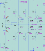
The build guide is actually correct.
Currently you do need to measure across R111A and R11B.
Test points TP101 and TP102 are NOT for this purpose.
Measuring across R111A and R11B with J103 installed is basically using the drivers as output transistors and R111A and R11B as output emitter resistors temporally to test the board.
I'll see what I can do to tweak the build guide and possibly add two more test points to the PCB's silkscreen moving forward.
For now you can Measure R111A or Clip on to one of your base resistors R114, R115, R116 etc
and R111B or Clip on to one of your base resistors R117, R118, R119 etc have a look at the schematic to verify.
Attachments
For now you can Measure R111A or Clip on to one of your base resistors R114, R115, R116 etc and R111B or Clip on to one of your base resistors R117, R118, R119 etc have a look at the schematic to verify.
On your schematic it looks like J101 and J102 could be useful to clip test leads on (if they are populated on the upper side of the PCB)
Yes, You can clip onto the jumpers J101 and J102.On your schematic it looks like J101 and J102 could be useful to clip test leads on (if they are populated on the upper side of the PCB)
However I would not recommend using your alligator clips as the main high voltage rail traces are just under these jumpers.
The use of small clip on multi-meter leads should be ok for this purpose, but if your using those you can probably clip onto the location shown in the build guide. 🙂
I have update the build guide and its now in the Dropbox folder.
Revisions are noted at the end of the file.
Hi Guys,
The Schematics have been updated to include the new test points TP107 & TP108
in relation to posts #951, #956 & #958
Please use your Dropbox link to access the latest schematic.
The Schematics have been updated to include the new test points TP107 & TP108
in relation to posts #951, #956 & #958
Please use your Dropbox link to access the latest schematic.
Here here! I think Stuart is on the road to creating one of the finest build guides in all of diyaudio! Kudos!
Best,
Anand.
Best,
Anand.
- Home
- Amplifiers
- Solid State
- DIY Class A/B Amp The "Wolverine" build thread