I just completed a EF3-4 using Sanken outputs and Toshiba drivers,
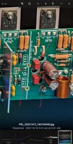
Your build looks great! Looking at the pictures of your board I am asking myself why you used the two small heatsinks but omitted the third, biggest heatsink for the driver transistors (?).
With the EF3-4 the builder have the option to mount the driver transistors on the main heatsink.Your build looks great! Looking at the pictures of your board I am asking myself why you used the two small heatsinks but omitted the third, biggest heatsink for the driver transistors (?).
Attachments

Thanks Stuart, but what about the EF3-3 version? Looks like I have to unwrap the boards and take a look..With the EF3-4 the builder have the option to mount the driver transistors on the main heatsink.
Looking good Gareth 👍Making progress on my build.
Both boards working perfectly power up and bias wise on 71Vdc railsView attachment 1100268View attachment 1100269
Hi Berlusconi,Obviously, this amplifier has a great potential, but to attain such results there must be something more. Could you, please, tell us what are the most important practical details that lead to such an extraordinary result.
This amplifier has been heavily optimised through simulation and measurement and then modification to achieve high performance.
If you have a look at the circuit on the first page of this thread it will give you an idea of some of the techniques involved.
- Daniel
Sound like a good class d amp.Ouah. Je suis si heureux qu'il soit opérationnel. Le premier amplificateur Wolverine à fonctionner en dehors de notre équipe de construction. Toutes nos félicitations:à votre santé:
Sound like a good class d amp.
Wolverine is an amazing CLASS AB amp.
To be honest all the hard work has been completed for us, with the tireless effort of the design team. The 1000's of hours that group put into this amplifier is what makes it perform the way it does.Obviously, this amplifier has a great potential, but to attain such results there must be something more. Could you, please, tell us what are the most important practical details that lead to such an extraordinary result.
All it takes in the end is to follow the build guide to the letter, ask questions if you are unsure, and match transistors/resistors that need so.
To be clear though it is not an easy task to measure this amplifier at the low levels of distortion that it produces, all I was showing was what it is capable of, and I still think it will measure lower still.
EF3-3 drivers are heatsink mounted only, there is no provision to mount on the main heat sink under the board.Thanks Stuart, but what about the EF3-3 version? Looks like I have to unwrap the boards and take a look..
A measurement with AP would bring clearer results than a THD magnifying glass.To be clear though it is not an easy task to measure this amplifier at the low levels of distortion that it produces, all I was showing was what it is capable of, and I still think it will measure lower still.
This is false too. I do not understand why you keep hammering this thread with lies. The AP uses notch filters which is the same thing I did. The measurements I made are solid and repeatable.A measurement with AP would bring clearer results than a THD magnifying glass.
BTW I am still waiting for your measurements.
Indeed. I have spent lots of efforts and money to be able to measure audio equipment. And I still lag behind: yesterday I was able to measure 0,00047 THD, which is way too rough for amplifier ot this quality class. Perhaps I will invest more.To be clear though it is not an easy task to measure this amplifier at the low levels of distortion that it produces, all I was showing was what it is capable of, and I still think it will measure lower still.
But, I still maintain that these computer-aided measurements, however rough, are of the paramount importance, not just to measure distortion but also to identify sources of noise, hum and buzz, to identify problems with wiring etc. I simply don't understand these who rely just on listening. From my experience in industrial applications I know that just equipment that measures good may work good. And Wolverine measures amasingly good.
I know that the mjl21193/94 are not recommended for this amp anymore, but can you guys measure the hfe of some of them ?
The datasheet says that the hfe for these transistors should not be more than 75 and I have a bunch of 21193 with the hfe between 90 and 103, while the 21194 will measure between 33-41.
The datasheet says that the hfe for these transistors should not be more than 75 and I have a bunch of 21193 with the hfe between 90 and 103, while the 21194 will measure between 33-41.
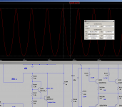
Very high VBE ripple. Please see screenshot.This is false too. I do not understand why you keep hammering this thread with lies. The AP uses notch filters which is the same thing I did. The measurements I made are solid and repeatable.
BTW I am still waiting for your measurements.
Attachments
@diyralf: that's not a measurement. I would suggest this amplifier is not for you and to look elsewhere. There was team a team of people who combed over every inch of this amp. Of course, you could always ,build and amp with your changes and then post actual measurements, that would be interesting.
Why should I measure when I can simulate? Too bad if the amp isn't further improved.@diyralf: that's not a measurement. I would suggest this amplifier is not for you and to look elsewhere. There was team a team of people who combed over every inch of this amp. Of course, you could always ,build and amp with your changes and then post actual measurements, that would be interesting.
I wasn't aware you were in possession of the highly optimized sim file the wolverine team has?Why should I measure when I can simulate? Too bad if the amp isn't further improved.
To the Wolverine development team, et al - just ignore the Trolls, they obviously have nothing better to do than to pick holes in anything they're not involved with. We mere mortals believe you've ALL done a terrific job!
His profile shows that this particular one has left predominantly negative comments, disagreements and complaints on numerous other forums as well ....
'nuff said
His profile shows that this particular one has left predominantly negative comments, disagreements and complaints on numerous other forums as well ....
'nuff said
What are you even measuring?Why should I measure when I can simulate? Too bad if the amp isn't further improved.
Your post is not clear.
Unless you have the Bom you don't know what the values of key components are.
We also have highly accurate simulation models for the transistors which you will not have.
Also your simulation file looks very basic. Our simulation file takes trace capacitance and inductance into account with values that we actually tirelessly measured on a real board.
Last edited:
- Home
- Amplifiers
- Solid State
- DIY Class A/B Amp The "Wolverine" build thread