Copy on the 2.2 ohm resistors.
Did you follow the suggestion in the wiring guide for the cap to chassis? Yes
I do have a couple scopes and will have a look...
Thanks for the next move forward
Scott
Did you follow the suggestion in the wiring guide for the cap to chassis? Yes
I do have a couple scopes and will have a look...
Thanks for the next move forward
Scott
Enjoy ...its only a mp3 file 48k
Recording from a simple Redmi Note 5.
Μy neighbors seem to have a lot of patience.
Recording from a simple Redmi Note 5.
Μy neighbors seem to have a lot of patience.
Last edited:

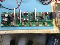
Well crap, about every 5 or 6th build I run into problems I guess I was due. I am building the EF3-3 using the latest Q107 - Q108 Q103 R109 500 ohm configuration. When I power up to 35V all leds light up however I have 0ma on TP107-TP108, Q105-Q106 and Q104 get warm.At 35V positive rail pulls 12mv negative 16mv. It does this on both boards one is hotter. I have j103 jumped and input shorted and a 9.1 k resistor soldered parallel to R17. I stoped at this point, Some assistance would be greatly appreciated.
Bill
Bill
Attachments
@wirewiggler
Your post is a little confusing did you mix up mV and mA.
To find the source of the problem I'd suggest double checking all transistors especially the capacitance multipler ones are oriented correctly and the legs of the others are also completely isolated from the heatsink. Id also suggest that you test each board individually to help you isolated the issue. Look up the trouble shooting section of the build guild for details.
You may also want to re route your NFB wire it should be lower and not running over that mounting hole.
The voltage across TP107 TP108 will be low unless you decrease R109 did you try that?
Ok, stupid me thought j101 j102 were not supposed to be in yet, put them in now cannot adjust bias below .99 v on either board.
That may have caused a problem as the negative feedback was not connected. I suggest that you test each board individually as outlined in the trouble shooting section.Ok, stupid me thought j101 j102 were not supposed to be in yet, put them in now cannot adjust bias below .99 v on either board.
ok everything seems to be dialed in so looks like it is time to start drilling & tap the heatsinks, oh joy.
Thanks, this is the most complex amp I have built so happy to be where I am.
Thanks, this is the most complex amp I have built so happy to be where I am.
I can say that the EF3-3 boards with the MJL4281 /MJL4302 are a good choice. They might possibly best choice available now from authorized sources i used them in my EF3-3 build and gave them a tuffy test with 4 paralelled focal towers shows 2.7 ohms on my fluke 87 III and i pushed it hard for several hours. I have 5U heatsinks and they got warm but amp never faltered its quick to respond to temp changes and these outputs have very good SOA. This is best sounding Amp i have ever owned and i will Never Sell it i am going to build EF3-4 and they will be my last amplifiers they are that good I love my WolverineI cant find the graph, but the EF3-3 with MJL4281 / MJL4302 outputs will work for you. I would not use the outputs you listed above
@Michael237
5U heatsinks? 400x210 ?Dimensions of them ?
Do you measure the temp on heatsinks at high levels music?
5U heatsinks? 400x210 ?Dimensions of them ?
Do you measure the temp on heatsinks at high levels music?
Last edited:
Haven't build my Wolverine yet I so can't comment on the heat from this thing, but normally I meassure temps at both channels at idle and when the amp is driven somewhat hard to check "worst case" temperatures is still within reason and not uncomfortable hot to the touch. And some probing around with a tempgun inside doesn't hurt just to clarify a good working condition throughout even at hard loads🙂
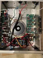
Got the amp in its case. There was some hum so I tweaked around with grounding and cables. Now it’s (almost) silent and I’m listening to it as I write this😁
Yes, I did change input cap and it makes a difference to the better! The amp is clean and accurate to whatever you feed it with and at “all” listening levels. Great sound!
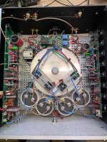
It’s a 5U case, weight around 35kg, mainly due to 1500VA transformer. Put on some handles so wife can help me carry😊
Thanks to the team and the support🙏
Yes, I did change input cap and it makes a difference to the better! The amp is clean and accurate to whatever you feed it with and at “all” listening levels. Great sound!
It’s a 5U case, weight around 35kg, mainly due to 1500VA transformer. Put on some handles so wife can help me carry😊
Thanks to the team and the support🙏
Attachments

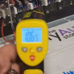
No i did not measure temps the heatsink temps it has never been past warm the protection circuit is so quick to adjust that it has never allowed it to get hot i will check with IR thermometer and post next time i have it fired up and post it . On a side note even though its an EF3-3 it never clipped before i said my ears said enough it plays loud effortlessly i am truly impressed with the clean output this amp just sounds right i have hooked up direct then with an old B&k PT3 and through onkyo RZ820 AVR it did not matter much what I pumped signal through it just sounds Good this amp will be my daily driver from here out@Michael237
5U heatsinks? 400x210 ?Dimensions of them ?
Do you measure the temp on heatsinks at high levels music?
i bought 5U deluxe case from DIY audio store they are in pics i posted when i first fired up and tested i think page 130@Michael237
5U heatsinks? 400x210 ?Dimensions of them ?
Do you measure the temp on heatsinks at high levels music?
I played few cds with vol close to clipping 106 is high heatsink temp using Farenheight temp scale the plastic encapsulation on transistors showed 112 so the 5U heatsinks are more than up to the task. If you theoretically add 4th thansitor pair and increase the temp 25 percent would max at 132 133 so its still running at very accrptable temps
Attachments
This is not to dislike your build at all, but those inputcaps might act like big antennas on the inputsection🙂 I don't believe these belong in a poweramplifier for the same reason.Yes, I did change input cap and it makes a difference to the better!
That said, in my current amp I have a 10uf Nichicon Muse BP with a WIMA 0.1uf MKP4 in parallel at the input stage. I have a cap-bypass option and to be honest, the difference in sound quality is absolutely minimal. No cap is best, but really no biggie...
I do experiment with foilcaps in the more friendly environment of my preamp, witch to my ears does provide some better midrange, or placebo.. who knows🙂
Best regards
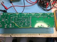
I've followed all the info to minimize ground loops and there seems to be a few builders that say "Now it’s (almost) silent". I have the same problem...very faint hum and worse if I touch C1. With the inputs shorted, no hum.This is not to dislike your build at all, but those inputcaps might act like big antennas on the inputsection🙂 I don't believe these belong in a poweramplifier for the same reason.
That said, in my current amp I have a 10uf Nichicon Muse BP with a WIMA 0.1uf MKP4 in parallel at the input stage. I have a cap-bypass option and to be honest, the difference in sound quality is absolutely minimal. No cap is best, but really no biggie...
I do experiment with foilcaps in the more friendly environment of my preamp, witch to my ears does provide some better midrange, or placebo.. who knows
So my question is in the ground lift area of the input. Most pro audio amps have a switch and normaly this only applies to pro-audio equipment with XLR (balanced) inputs. Can this Wolverine amp be modified for a jumper to deal with the ground lift? I do see that there is a connection between D5 and D6 that goes to the GLIFT, would said jumper have an effect in this part of the circuit?
Side note: I've built a few amps that just have the RCA shield connected to PS 0v and all my older audio amps are the same way and NONE of them have Any Noise.
Thanks All
Scott
Hi @90scaraudio, sorry to hear that you are still experiencing a little hum. How did you go with my suggestions? Did you measure the output noise of you source? If so, what was it.
It would be great if you could post a few photos.
1. You chassis, the more the better.
2. A oscilloscope plot of your source, AC coupled.
3. A oscilloscope plot of the output of the Wolverine, AC coupled.
Another thing that can cause noise is a ground loop from your power outlets. Do you have the source and the amplifier plugged into the same power outlet?
You can try disabling the DC offset adjustment by removing D5, D6 and R22 but I don't suspect that will do anything.
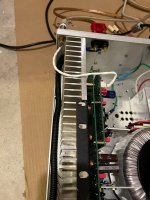
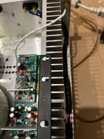
Thanks Stuart. I did make some improvements. As I said before, the hum would get louder if I put my hand close or touch C-1.
So as a test I replaced the LARGE 10uf 600v (C-1) caps with Wima 0.15 63v caps. The hum is so very slight now that I can live with it.
I also cant hear much of a difference with the Wima caps.
the amplifier is plugged into the same power outlet. Yes I know from working Pro audio gear and setting up stages that the equipment will get bad hum if plugged into a different phase of the power source... (One plugged into L1 of the Electrical panel and some other gear plugged into L2).
I did not sniff around with my O-Scope, (Time and honey do list's)! Sorry.
Please don't be to hard on my install.
Attachments

- Home
- Amplifiers
- Solid State
- DIY Class A/B Amp The "Wolverine" build thread