
Totally misread the schematic - so big thanks @mhuth1776 for alerting me. I see now that Q104 says "ambient" and Q103 says "mount to h/s". Another reason not to do hobby time at 11-2am because you can't wait to the weekend.@bullittstang given you are using the new bias transistors, Q104 is no longer mounted to the heat sink. Q103 is on the main heat sink with fly wires in an EF3-3.
I will fix and re-bias the channels.
EDIT: any issue keeping the Q104 mounted to the heatsink under the board? Just trying not to unsolder and bend the legs again if not necessary??
Last edited:
Doing so will result in excess compensation. The circuit is setup to have Q104 an ambient sensor and Q103 the output thermal sensor.
If you leave 104 on the main heatsink, it will track the output temperatures instead of the local ambient.
If you leave 104 on the main heatsink, it will track the output temperatures instead of the local ambient.
Thanks for the explanation and makes sense as I think about it and read your answer.
Both channels now have updated bias compensation - Q104 free standing (ambient) and Q103 attached with flying leads to Q111. Bias set to 42mV, CCS at ~5.0V both set without issue. Now to heat soak them, re-check everything and maybe get some make-shift connection to my pre-amp, so I can have some music. Now... back to the chassis.
Both channels now have updated bias compensation - Q104 free standing (ambient) and Q103 attached with flying leads to Q111. Bias set to 42mV, CCS at ~5.0V both set without issue. Now to heat soak them, re-check everything and maybe get some make-shift connection to my pre-amp, so I can have some music. Now... back to the chassis.
Parts selection, soldering, wiring, ... everything is important. But in the end, it's also about optics 😎

I WANT THOSE GAUGES!... where do you get them and how to wire them.... 😁optics
The ones I used were similar to these:
https://de.aliexpress.com/item/4001211032454.html
(I used a yellow version with LED backlight - gives this sort of steampunkish look)
https://de.aliexpress.com/item/4001211032454.html
(I used a yellow version with LED backlight - gives this sort of steampunkish look)
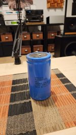
Weird question, i am building second power supply for second wolverine, what's maximum capacitance recommended/allowed?
Hi Adason,
What sort of transformer and rectifier setup do you have or plan to use ?
This information can help to decide on what is required
- Dan
What sort of transformer and rectifier setup do you have or plan to use ?
This information can help to decide on what is required
- Dan
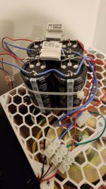
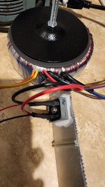
Nice capacitors.
You may want to consider RC snubbing large Electrolytics.
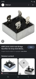
What model rectifiers ? I would check peak current capability. Just to be safe.
Hope this helps
- Dan
You may want to consider RC snubbing large Electrolytics.
What model rectifiers ? I would check peak current capability. Just to be safe.
Hope this helps
- Dan
I have abandoned big caps idea. Too much stress on toroid. Will just put bunch of small caps in parallel to make smaller usual value.
- Home
- Amplifiers
- Solid State
- DIY Class A/B Amp The "Wolverine" build thread