I was going to do this, but the project was taking me so long I figured why not go straight to the fancy pots. I'm in no hurry.why don't you try the 6-24AXO with the 50kOhm - trimpots (at the input-buffers) recommended by Nelson Pass?
Guess I was wondering if/when I decide to swap out the pots, if I could get away with dropping one on each channel for lower cost. I'm assuming there will always be at least one pot per channel set on 0Ω rendering it useless? Unless there is another reason I'm missing?
The only thing as a beginner I can think of is if the input voltage is somehow too high for the amplifier. For the foreseeable future I'll be feeding it 2VRMS max i think.
@Ramblr you have a very nice looking build. I do have one concern about your chassis grounding scheme. Unless I am missing a wire in the photo you posted, it looks like you only connected the screen of the transformer to the safety ground on the IEC connector. The chassis should be directly bonded to the safety ground so if a wire falls off or a transformer fails the chassis will be kept at ground potential.
Hello seanc,
yes, this connection is missing in the schematic. 😗Was mentioned a few times in this thread.
Check my post #1584 / pic 2 and also from others....
Cheers
Dirk
yes, this connection is missing in the schematic. 😗Was mentioned a few times in this thread.
Check my post #1584 / pic 2 and also from others....
Cheers
Dirk
That connection is NOT present on the PCB. If one selects a third order filter, the calculation must include the superfluous resistor and pot values. It is also possible to short the resistor and/or pot, but then the flexibility of eventually selecting fourth order is compromised. I did it and it's not difficult to revert to stock. I wonder if this was an error, or was simply impossible to implement in the board layout, which is already a marvel of design.
I recall that it was deliberate. Perhaps it would have been better to have included a jumper...
😎
😎
@Ramblr you have a very nice looking build. I do have one concern about your chassis grounding scheme. Unless I am missing a wire in the photo you posted, it looks like you only connected the screen of the transformer to the safety ground on the IEC connector. The chassis should be directly bonded to the safety ground so if a wire falls off or a transformer fails the chassis will be kept at ground potential.
You are correct I did not ground the chassis. I will fix my oversight. Thank you pointing out my mistake, as a new builder its much appreciated.
What kind of power supply is that? Regulated?
It is from Antek. Look under their power supply section. Transformer and rectifier in one package. Non regulated. My thought was is it has to be better than a wall wart. Is the power supply section of the board not enough? Should I build a super regulator board to add to it? I know enough to be dangerous as can be seen in my missing chassis ground.
Hi there is this link still working for anybody? https://doublesecretlabs.com/apps/passxo/
I can only see a sample wordpress page.
Thanks.
I can only see a sample wordpress page.
Thanks.

Ordered three ladder pots for my build. Once I had them in my hand, I realised I'd made a mistake. These are supposed to be linear pots for level control, not logarithmic yeah?
I've been trying to track down strange sounds from the right channel high pass section of my crossover (posts 1,203 and 1,560). At first I thought it was the jfets; replaced them all. Problem not solved.
It turns out that four of the biasing resistors were the wrong value (100 ohm instead of 68 ohm). I stupidly didn't check them before installing (since they came matched to the jfets, I didn't know what value they should be, and the bands were all the same). And by an incredible coincidence they all ended up in the same section of the board (the offending channel). They're now replaced. However I now have a new problem. Out of the circuit they measure 68 ohm. Once installed, two of them still measure 68 ohm; but the other two measure only 50ohm. I take them out: 68 ohm. I put them back in: 50 ohm. They're at the position shown in the attached photo.
Why would this happen? Every other biasing resistor on the board measures 68 ohm. And is this a problem? Just to be sure I replaced the two jfets they were biasing, but that didn't change anything.
Could the board itself be faulty?
Any help gratefully received!
Attachments
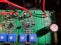
No. It's just the impedance of the fet in parallel with the rest of the circuit. Try reversing the lead from the ohm meter.
https://web.archive.org/web/20230117112855/http://doublesecretlabs.com/apps/passxo/check internet archive wayback machine
Meinolf
What is best practice if I want the low end channels to feed two amps? As in I want to bi-amp a pair of dual VC drivers from the two low pass channels. Do I need an additional buffer, or can I simply split the channels in the wiring layout?
Perhaps I'm misunderstanding your question @Haze Head, but I assume you are wanting to drive two mono-block amps. If that is the case, you shouldn't need to do anything to the crossover. One low-pass output to your right channel and one to your left.
Yes I believe there is a misunderstanding, he wants to basically parallel the 2 x LF outputs to 4 channels.
I think 😄
I think 😄
- Home
- Amplifiers
- Pass Labs
- DIY biamp 6-24 crossover