My sound system is a 5-way setup, how many kits will I need - my guess is 3 ?
And how would the kits connect together ?
Common PSU etc.. ?
I have one kit already so I will start to build that one up to test.
And how would the kits connect together ?
Common PSU etc.. ?
I have one kit already so I will start to build that one up to test.
I required two kits for my 3 way. For a 5 way, I believe you would need 4 kits. Each board has 4 filters. 1 filter would be for low pass (LP), 2nd filter would be for HP which would be feed to filter 3 which is LP which output would make your first band pass, 4 and 5 for second BP, 6 and 7 for third BP and 8 for final HP. So 8 channels (two boards) to do 5 way for left channel and another two boards for right channel. To make the band pass the output of HP just forward of the 10uF output capacitor is jumpered to the LP at the output of the buffer stage (bypasses uneeded circuitry). Yes, on the common supply.
Attachments
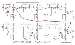

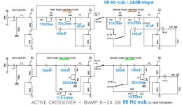
6-24 AXO - SUBWOOFER (80 Hz / 24dB/octave)
Hello 6-24 AXO - builders,
a forum-member asked me, if I could give him the datas (R- / C- values filter) of my build. Sure!
These values are chosen to use the 6-24 AXO as a subwoofer crossover. I prefer crossover frequencies
around 80 - 100 Hz.
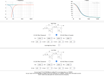
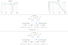
In the first pic, you can see the simulation in M: Rothachers filter simulation program:
http://doublesecretlabs.com/apps/passxo/
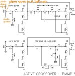
The second pic shows shows these R- and C-values adapted to the 6-24 AXO schematic from Nelson Pass.
The R-values (in blue) have to be adjusted. You have your 10 kOhm resistor followed by the trimpot in series.
For a R- value 17.5 kOhm = 10 kOhm + Trimpot adjusted to 7.5 kOhm...
This is one version. Feel free to adjust filterfrequencies to your needs.
Cheers
Dirk😉
Hello 6-24 AXO - builders,
a forum-member asked me, if I could give him the datas (R- / C- values filter) of my build. Sure!
These values are chosen to use the 6-24 AXO as a subwoofer crossover. I prefer crossover frequencies
around 80 - 100 Hz.
In the first pic, you can see the simulation in M: Rothachers filter simulation program:
http://doublesecretlabs.com/apps/passxo/
The second pic shows shows these R- and C-values adapted to the 6-24 AXO schematic from Nelson Pass.
The R-values (in blue) have to be adjusted. You have your 10 kOhm resistor followed by the trimpot in series.
For a R- value 17.5 kOhm = 10 kOhm + Trimpot adjusted to 7.5 kOhm...
This is one version. Feel free to adjust filterfrequencies to your needs.
Cheers
Dirk😉
Attachments
Hi all, I've just ordered two kits and I already have a B4. I have a question about phase shift and using two of these 6-24's and a B4.
I have a 4 way system so I plan the following. Firstly feed the full range signal into one 6-24 and Low pass (LP)to a sub woofer at 80hz, then High Pass (HP) to the next 6-24, where I'll LP to a midbass cabinet at 500hz and HP to the B4 where I'll finally LP to a horn at 5000khz and HP to a tweeter.
So everything in my system is physically time aligned. But my head is spinning thinking about phase shifts and delays. Any advice on how to best mitigate that please?
@goldjazz
just my 2cents but i'd rather use the B4 at first stage - split at 500Hz and then feed the signals into the two 6-24 networks so each signal will have the same pathlength.
cheers
Attila
just my 2cents but i'd rather use the B4 at first stage - split at 500Hz and then feed the signals into the two 6-24 networks so each signal will have the same pathlength.
cheers
Attila
Ok thanks also for this tip. So phase shift/time delay and also noise (distortion?) Are things I'll be listening out for and trying to measure for in REW as I try these various configurations of the active xover. I'm also going to look at a passive filter between the HF horn and the UHF bullet tweeters. I think quad amping is potentially a bit complex and a bit unnecessary. I think there are advantages of being able to chose seperate amplifiers on the sub woofer, midbass box, and HF section, but probably not for the tweeter.
My PA system is quad amped and it definitely benefits from it.
In the future I may take it up to 5-ways with an extra set of speakers around the 450Hz point to increase SPL.
In the future I may take it up to 5-ways with an extra set of speakers around the 450Hz point to increase SPL.
I'm currently quad amping. I thought to do a passive between the hf horn and bullet tweeter because they are both compression drivers, with similar efficency. so I thought the one amplifier would be suitable for both and just put an lpad on the tweeter along with the passive network. My other reasoning is i prob want to put somekind of protection on the hf horn and bullet as well, so i'd need a capacitor there anyway. But I'll certainly compare passive vs active for this xover point and report back what I'm noticing.
I left the passive network in my Alcons speakers as a backstop to protect the tweeter as well.
But disconnected the woofer from it and fed it separately.
Otherwise just one tiny error and its bye bye to a zillion Euro PA ribbon.
The sound was definitely better as the passive cross-over, although top quality, creates some effects into the tweeter from the woofer side.
But disconnected the woofer from it and fed it separately.
Otherwise just one tiny error and its bye bye to a zillion Euro PA ribbon.
The sound was definitely better as the passive cross-over, although top quality, creates some effects into the tweeter from the woofer side.
Attachments
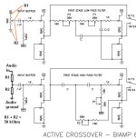
Hi everyone, it's been great reading through the thread. I'm building one to crossover mains and sub. I've got separate volume control for the mains and the sub so I could use fixed resistors instead of input pots. I'm not sure I will but I'm interested to know how I'd do this.
My source into the crossover is about 800ohms output impedance so I'd be looking to maintain an input impedance of 10kohms or more. What kind of resistor values would I be looking at and how would I wire considering input, output and wiper?
My source into the crossover is about 800ohms output impedance so I'd be looking to maintain an input impedance of 10kohms or more. What kind of resistor values would I be looking at and how would I wire considering input, output and wiper?
Hello Gabba,
the trimpots wiper is connected to the input of the inputbuffer (whether to the lowpass or highpass).
Turn your trimpot fully counterclockwise and measure with your DMM to which contact the resistance is the highest. Measure from wipercontact to the two other pins of your trimpot.
The contact which offers highest resistance to wiper is your input for the audiosignal; the other (third) contact
(with close to 0 Ohm resistance to wiper) gets connected to audioground.
Nelson Pass used 50 kOhm trimpots. You can also use 25 kOhm.
You could listen to your setup and adjust your volume trimpots of the 6-24 AXO to the desired needs of your amps / speakerdrivers. Then you could measure the resistance of the (input volume) trimpots and exchange
to fixed resistors.
I only ask myself, if this makes sense with an active crossover? It should be flexible / adjustable.
Perhaps one day you want to exchange an amp or speakerdriver in your active system...
Listening to music in which bass is recorded to loud / to silent...
Only some thoughts. 🤔
Enjoy your 6-24 AXO!
Dirk
Attachments
My crossover doesnt work as expected. The crossover result sounds wrong very obviously.
Can anyone help pointing out my mistake in setting?🤔
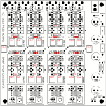
My aimed crossover point is at 1800 hz with 24db/octave. I used the resistor and capacitor value shown in the pic. In order to obtain a most accuracy result.
I use the resistor value calculated to replace the originally 10k resistor in series to P1 and P2.
I therefore turned 50k P1 and 50k P2 all the way down to 0 ohm.
The Board layout marked the resistor and capacitor used and its position placed.
Can anyone help pointing out my mistake in setting?🤔
My aimed crossover point is at 1800 hz with 24db/octave. I used the resistor and capacitor value shown in the pic. In order to obtain a most accuracy result.
I use the resistor value calculated to replace the originally 10k resistor in series to P1 and P2.
I therefore turned 50k P1 and 50k P2 all the way down to 0 ohm.
The Board layout marked the resistor and capacitor used and its position placed.
Attachments
"The 24 dB/octave case has been favored in the compromises in this
design, that is to say I expect it to be the most popular launching point for crossover
development, and the result is quite good. The only point to note is that the classic L-R
alignment will result from the P2 potentiometers to be at around 1/2 the resistance of the
other pots. "
"If you are dedicated to the 24 dB/oct L-R alignment, you can extend your frequency
adjustment range on this filter if you replace the high pass P2 50K pots + 10 Kohm resistor
with 25K in series with 4.7K resistors."
"The frequency pots go higher in frequency with clockwise rotation. The center point of the
resistance range is close to > mark on the board and using a small flat blade screwdriver you
would point the arrow on the rotating top of each pot to this spot."
Maybe these words of wisdom from Nelson could help you.
- Home
- Amplifiers
- Pass Labs
- DIY biamp 6-24 crossover