Hello 14071466d,
your resistor - values and cap - values are looking good. They also seem to be located correctly on the pcb.
I assume, something else is wrong.
Your voltages are correct on the 6-24 AXO - board?
You have used the JFets (J113) in the correct spots. Bias resistors are of correct value?
Highpass is really feeding the amp which is connected to the tweeter?
Lowpass is really feeding the amp connected to the mid/bassdriver?
Passive crossover is nowhere and not connected.
You have tried to adjust the volume between lowpass and highpass?
Only some basic questions... 🤔
Does it sound unbalanced between high and low?
Is it a kind of distortion?.
What kind of speakerdrivers are you using?
Some pics of your setup and the board of the 6-24AXO could also help.
Cheers
Dirk
I know there are the key paragraph to figure out how this crossover work properly. My understanding is when"The 24 dB/octave case has been favored in the compromises in this
design, that is to say I expect it to be the most popular launching point for crossover
development, and the result is quite good. The only point to note is that the classic L-R
alignment will result from the P2 potentiometers to be at around 1/2 the resistance of the
other pots. "
"If you are dedicated to the 24 dB/oct L-R alignment, you can extend your frequency
adjustment range on this filter if you replace the high pass P2 50K pots + 10 Kohm resistor
with 25K in series with 4.7K resistors."
"The frequency pots go higher in frequency with clockwise rotation. The center point of the
resistance range is close to > mark on the board and using a small flat blade screwdriver you
would point the arrow on the rotating top of each pot to this spot."
Maybe these words of wisdom from Nelson could help you.
resistrance at P2 position ( 50K pots potentiometer value + its resistor in series)
equals to
half of resistrance of P1
Then the high pass frequency crossover with Low pass frequency nicely ( assume that low pass frequency is set correctly as well)
Which also means the 50k potentiometer are for flexibility to adjust the crossover point. Since I already got a happy listening result using passive crossover at 1800 hz frequency. It should be reasonable to just adopt and apply this crossover frequency into 6-24 biamp board??? 🤣 Please correct me if i misinterpreted the instruction.
Is it ok to assume crossover frequency is nearly the same no matter doing it actively or passively????
Hello 14071466d,
your resistor - values and cap - values are looking good. They also seem to be located correctly on the pcb.
I assume, something else is wrong.
Your voltages are correct on the 6-24 AXO - board?
You have used the JFets (J113) in the correct spots. Bias resistors are of correct value?
Highpass is really feeding the amp which is connected to the tweeter?
Lowpass is really feeding the amp connected to the mid/bassdriver?
Passive crossover is nowhere and not connected.
You have tried to adjust the volume between lowpass and highpass?
Only some basic questions... 🤔
Does it sound unbalanced between high and low?
Is it a kind of distortion?.
What kind of speakerdrivers are you using?
Some pics of your setup and the board of the 6-24AXO could also help.
Cheers
Dirk
- You mean using multimeter to check voltage at specific points, to see if the circuit board is working correctly? I didnt really check because once the 24v is applied to the board, the led is lit and sound just come out in both channel. How can i check and confirm?
- The J113 and bias resistor are bought from Diyaudio as a matched value bundle.
- I am sure that the wire connection between speaker, power amp and crossover board are connected correctly.
- The volume setting cannot help much since it is very obvious that active board sounds totally difference to originally passive crossover board. The active crossover frequency is set way lower than 1800 hz,
- it sounds like tweeter is taking over too much workload than it should be. The woofer is lazy and absence in the show. The midrange is like a big void and not solid, The drum and bass is weightless and almost inaudible.
- The speaker is actually also a diy 2 way tower speaker. CSS audio Criton 2TD-X It sounds great with its orgianl 1800hz passive crossover. This is why I wonder if it can get even better with active crossover setting.
- Yes you are right, some picture may help figure out the problem. I will take some picture later tonight when I am home. Thanks for the help.
I turn all P1 and P2 on the board (both high pass and low pass to "bypass"the trimmer pot) all the way to the end in anticlockwise. I use 1 turn 50k Bourns trimmer. It should be nearly 0 ohm in this situation right?Your trimpots in the filters are really at 0 Ohm? Perhaps at full resistance?
Dirk
Do you know anything about the response of the passive crossover? As a start, you should try to use the same slopes, phasing and levels for the drivers.
#1606
I did studied a little bit about the original speaker design and how to recreate similar performance by this active crossover board.
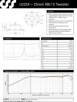
"Tweeter info" is the tweeter charateristcs.
"Woofer info" is the Woofer charateristics. Two identical woffer are wired in parallel for one channel. So half the impedence only.
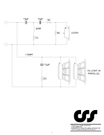
"original passive XO design" is the offical design crossover with passive component.
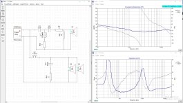
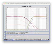
"XSim stimulation" is the simulation of orginal frequency response and impedence when all things combined together. The data of tweeter and woofer were extracted and applied to the simulation.
I did studied a little bit about the original speaker design and how to recreate similar performance by this active crossover board.
"Tweeter info" is the tweeter charateristcs.
"Woofer info" is the Woofer charateristics. Two identical woffer are wired in parallel for one channel. So half the impedence only.
"original passive XO design" is the offical design crossover with passive component.
"XSim stimulation" is the simulation of orginal frequency response and impedence when all things combined together. The data of tweeter and woofer were extracted and applied to the simulation.
Attachments

You need to give it a rest for a day or so then go through the pcb overlay and check the location of all the crossover parts.I turn all P1 and P2 on the board (both high pass and low pass to "bypass"the trimmer pot) all the way to the end in anticlockwise. I use 1 turn 50k Bourns trimmer. It should be nearly 0 ohm in this situation right?
I need the response from the drivers as they are mounted in the speaker.#1606
I did studied a little bit about the original speaker design and how to recreate similar performance by this active crossover board.
"Tweeter info" is the tweeter charateristcs.
"Woofer info" is the Woofer charateristics. Two identical woffer are wired in parallel for one channel. So half the impedence only.
"original passive XO design" is the offical design crossover with passive component.
"XSim stimulation" is the simulation of orginal frequency response and impedence when all things combined together. The data of tweeter and woofer were extracted and applied to the simulation.
Which also means the 50k potentiometer are for flexibility to adjust the crossover point. Since I already got a happy listening result using passive crossover at 1800 hz frequency. It should be reasonable to just adopt and apply this crossover frequency into 6-24 biamp board??? 🤣 Please correct me if i misinterpreted the instruction.
Is it ok to assume crossover frequency is nearly the same no matter doing it actively or passively????
Yes. Why don't you try adjusting the arrow on the adjuster of P1 to the v on the PCB. Measure the resistance between either pin 1 or 3 to pin 2, then adjust P2 to 1/2 that reading and see what happens. Worse thing is you have to adjust them back to your setting.
Hello 14071466d,
have you tried to invert the polarity of your speakeroutput at one amp?
This means + cable of tweeter /mid to minus output of amp and - cable of tweeter/mid to plus output of amp.
You can try this also with your tweeters/mids in correct püolarity and bass drivers connnected with inverted polarity to bass-amp.
All what you wrote above sounds good to me - or should be correct.
Cheers
Dirk
Hello elwood625,
his resistor values in the sallen-key-filters are o.k.. He used values without any resistance from the trimpots - could have also left the trimpots out and could have made a wire bridge in there. I hope the trimpots are really at 0 Ohm and not at 50 kOhm/ full resitance?
Only some thoughts... 🤔
Greets
Dirk
This is my impression.I know there are the key paragraph to figure out how this crossover work properly. My understanding is when
resistrance at P2 position ( 50K pots potentiometer value + its resistor in series)
equals to
half of resistrance of P1
Then the high pass frequency crossover with Low pass frequency nicely ( assume that low pass frequency is set correctly as well)
Which also means the 50k potentiometer are for flexibility to adjust the crossover point. Since I already got a happy listening result using passive crossover at 1800 hz frequency. It should be reasonable to just adopt and apply this crossover frequency into 6-24 biamp board??? 🤣 Please correct me if i misinterpreted the instruction.
Is it ok to assume crossover frequency is nearly the same no matter doing it actively or passively????
Your R values are too small looking at the Sim for the 50K trim pots. This is why your filters at off.
The R value should be the fixed value 10kohms plus 50% of the 50K trim pots (25 kohms) for the trim pot to be centred at 1.8 khertz.
So select your C values for about R equals 35K in the case of 50K trim pots. You may prefer to use 25K pots so the R value in your Sim is 22.5 kohms for the pit to be centred at 1.8 khertz.
This will need looking at the preferred values of C to get C/2
To set up the active crossover and test that it is working correctly use REW with a scarlet 212 interface to perform a frequency curve of each filter.
Alternatively measure your trim pot values before you install them.
These impedances are high but remember you are using Jfets here not opamps.
I would worry about the passive network. That will just confuse you. Simply aim for a 24 LR network @1.8 khertz.
Once you have tested the active crossover voltage drives then use REW to perform frequency response measurements to obtain a 1.8 khertz Acoustic crossover frequency. The electrical crossover points may end up being different to obtain the transfer function. The electrical polarity of the LR24 is in phase. Reverse the phase to confirm a phase null of about 20 db at the crossover point. By adjusting the Trim post you will obtain the phase null.
This is why need the trim pots centred at the design stage.
You have a lot of problems, and none of these responses addresses them.
You say you configured the 6-24 for 4th order, but your CSS crossover schematic clearly shows 3rd order for tweeter, 2nd order for woofers. Of course the wrong slopes will not sound correct. You cannot arbitrarily change the basic design of the speaker system and expect it to perform acceptably.
Also, if you turn your pots counterclockwise, that will make them the highest resistance, not zero. Turn them clockwise to obtain lowest resistance.
There is nothing wrong with your 6-24.
Post 1614 . That’s plain wrong.
The procedure l outlined is what Nelson
and l worked through when we evaluated the prototype active network.
This is diy. Do it your self. Be adventurous and learn as you progress.
There is absolutely no necessity to copy the passive network. As long at the transfer function works correctly in the crossover region.
Nelson clearly described how to do this in the project article.
The user can adjust the crossover using REW measurements as he likes.
This is diy.
It’s actually a very simple tower design based on a smaller version. A forth order network was likely too complicated and costly for that kit. Besides which the woofer extends well past the 1.8 khertz crossover point.
Sometimes 12/18 db electrical network are used depending on a number of factors including tweeter power handling and the vertical polar response.
We are not concerned with a microscopic deep dive into Vitulux here. That is only a simulation. Professional engineers use a simulation as the start of the process before voicing a system with human ears. Often the crossover will be modified to incorporate passive EQ within the filters via a carefully crafted voltage drive.
The benefit of going active is that user can more easily alter the filters to fine tune the systems to his own preferences. The process of empirically modifying a passive network is both tedious and very time consuming.
Looking at the drivers both the woofer and tweeter response are for diy purposes textbook. There is very little inductance in the woofer.
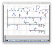
I will model and reverse engineer the passive voltage drive in Leap 5 later today. Then provide the exact RC time constants for the active version if the user desires to copy the passive network.
The procedure l outlined is what Nelson
and l worked through when we evaluated the prototype active network.
This is diy. Do it your self. Be adventurous and learn as you progress.
There is absolutely no necessity to copy the passive network. As long at the transfer function works correctly in the crossover region.
Nelson clearly described how to do this in the project article.
The user can adjust the crossover using REW measurements as he likes.
This is diy.
It’s actually a very simple tower design based on a smaller version. A forth order network was likely too complicated and costly for that kit. Besides which the woofer extends well past the 1.8 khertz crossover point.
Sometimes 12/18 db electrical network are used depending on a number of factors including tweeter power handling and the vertical polar response.
We are not concerned with a microscopic deep dive into Vitulux here. That is only a simulation. Professional engineers use a simulation as the start of the process before voicing a system with human ears. Often the crossover will be modified to incorporate passive EQ within the filters via a carefully crafted voltage drive.
The benefit of going active is that user can more easily alter the filters to fine tune the systems to his own preferences. The process of empirically modifying a passive network is both tedious and very time consuming.
Looking at the drivers both the woofer and tweeter response are for diy purposes textbook. There is very little inductance in the woofer.
I will model and reverse engineer the passive voltage drive in Leap 5 later today. Then provide the exact RC time constants for the active version if the user desires to copy the passive network.

Briefly outlined below is a work flow to obtain the desired active filter design.
Obtaining first an active filter realisation of the original passive network using voltage drives was felt appropriate where the user may not yet have the means to obtain accurate indoor FR measurements.
Notes:
If the user has the means to obtain indoor measurements competently then there is no reason that an alternative active filter ie 24 db slopes could be designed (incorporating baffle step or other desired driver EQ). Less crossover region overlap generally means less vertical polar pattern irregularities. See my summary.
1. Modelling of the woofers in Leap to obtain a close approximation of the impedance curve of the CSS woofers.
2. Input of the passive schematic provided by CSS Audio for the Criton 2TD-X kit.
3. Simulation of the CSS Audio Criton 2TD-X kit schematic to obtain the passive network voltage drives for the woofer filter and tweeter filters using the impedance modelling.
4. Curve fitted Objective Target curves for the passive filter voltage drives. See notes.
5. Modelling of the active low and high pass filters to fit the Objective Target curves.
Notes:
Fortunately the Objective Target curve in the Leap Optimisation Engine for the woofer(s) voltage drive fits a 2nd order Linkwitz low pass filter with -6 db point of 750 hertz. This closely matches the passive network voltage drive.
The Objective Target curve for the tweeter voltage drive fits a 3rd order Butterworth filter with a -3 db point of 2,000 hertz.
These are voltage drive target curves not FR response target curves.
Based on the passive voltage drivers of both the tweeter and the woofer the tweeter is attenuation some 6 db in the passive network.
The woofer low pass passive filter incorporates some response shaping EQ above 750 hertz.
6. Run active filter schematic realisation for both low and high pass filter to fit the desired R resistance values including the 50K ohm trim pots. The C values provided by Leap Crossover Shop are preferred C values. This will allow the 10K ohm R values with approximate centre position of the 50K trim pots. There is more than enough trim in the pots to make for any minor variations between the passive network and the active network filters.
On the basis of the above I recommend :
The user first measure the passive Criton 2TD X system with REW as a system and the individual drivers.
Measure the drivers mounted on the baffle in free space with the passive network.
Apply the above active design and again measure with REW.
This will enable the user to consider other active crossover filters which can be designed to fit the loudspeaker system (the drivers and the baffle).
Summary
None of this is rocket science and is an appropriate routine for obtain an equivalent active filter from a passive system network.
It should be pointed out that passive network realisations are not set in stone and the adoption of alternative active filters can provide some performance improvements where a passive network is not practical.
The link below is an excellent template for anyone to fully appreciate the process of designing an active loudspeaker system.
https://www.ti.com/lit/ug/tidu035/tidu035.pdf?ts=1722418573418&ref_url=http%3A%2F%2Fwww.ti.com.cn%2Ftool%2Fcn%2FTIPD134%3FHQS%3DTI-null-null-DS5-refdes-rd-null-cn
Attachments
Last edited:
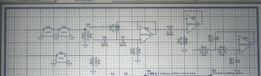
Referring to the way in which the Jfet buffer schematic is set up only the C values are relevant in the realisation schematic from Leap which uses op amps.
I chose those R values for continuity of the pot values. The pots are there only to offer a range of crossover frequency either side of the desired crossover point .
Normally a sallen key Opamp filter uses R values of no more than 3kohms. It’s not appropriate to load these Jfet buffers with those values. A Sallen Key filter can be set up with equal or non equal values (ref Doug Self text Designing Active Filters)
The user can check the sim offers by NP to validate the working values for the kit.
Attachments
Last edited:
As a final thought the user might eventually consider making this 2 way system a 3 way design. For example using the CCS new 6 inch mid bass driver just like their 3 way kit if he wants a better loudspeaker than the two way system. This 3 way system has superior directivity in the midrange.
https://www.css-audio.com/online-store/CSS-Criton-3TD-X-Kit-Pair-p644003321
The 3 way design could be bi amped between the woofers and the midrange with the passive network with the tweeter using the process l outlined above to obtain the response characteristics. The midrange passive network would need to be reworked as it would only be a low pass filter.
This would offer the benefit a significant improvement in dynamic performance over the passive 3 way system. A high performance amplifier could be used on the midrange and the tweeter further pushing the performance envelope. It would also reduce the cost of the 3 way passive network.
Attachments

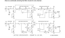
Low pass filter.
In the attached schematic from the crossover kit instructions see the custom LR 12 db low pass filter with the R value designation SLR1 and SLR2.
As the CSS Criton low pass filter has a -6 db voltage drive point at 750 hertz SLR1 and SLR2 should be 43 Kohm.
So looking at the standard crossover schematic deduct the 10kohm fixed resistor value to obtain the trim post value of 33kohms (adjusted before installation). Note here the C values must be 5nF.
Set the switches to 12 db on the low pass filter.
Attachments


Last edited:
- Home
- Amplifiers
- Pass Labs
- DIY biamp 6-24 crossover