Another crossover is born, it lights the LED, no idea if it lets music through, I guess lots of messing with pots is in my future. Was a fun project and I ended up using some of those "Leaky" green sleeve caps to boot. Hoping to use this with Kef ls50 80hz high pass and then maybe try to run my sub off the low pass at 80hz as well with 24 DB slopes to start out.
Cheers
Cheers
Attachments

I recently decided to upgrade my 6-24 crossover by replacing the J113 JFET's with LSK170's purchased from the diyAudio Store.
As Nelson would say: Don't forget the K170's have different pins placement compared to the J113.
It's not hard to bend the pins to fit, I used a magnifying glass to check for shorts.
Is there a specific thread for this power supply filter ? I have a question but don’t want to hijack this thread..With V+ = 36 volts and V- = 0 volts and NPN (Q2) VBE = 0.7, I calculate that Q2 turns on, and the relay pulls-in, (and the muting stops, and the amp begins to drive the speaker load), about 2.9 seconds after power is applied.
math:
Vthevenin = (2.2 / 29.7) * 36 = 2.67 volts
Rthevenin = 2.2K // 27.5K = 2.04K ohms
Tau = Rthevenin * C7 = 2.04E+3 * 4.7E-3 = 9.6 seconds
V_NPN_base(t) = Vthev * (1 - exp( -1.0 * t / Tau ) )
0.7 = 2.67 * (1 - exp( -1.0 * t / 9.6 ) ) ... solve for t, the time at which V_NPN_base equals 0.7V
t = 2.9 sec
Thanks
It’s all good, my own tiny PCB is working and the turn on delay is 15 sec instead of 3 sec 👍
Thanks for sharing your design Mr Pass 😀
Thanks for sharing your design Mr Pass 😀
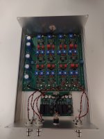
@gsrchrisu : what about those small boards in that photo above?
https://diyaudiostore.com/collections/kits-power-supply/products/smps-dc-filter-p089zb-kit
Hello Diyers !
I configured the boards for a 24db/oct 800hz Crossover.
Everything seems perfect but measuring the board with my external soundcard and playing with all the options, the best I can measure is this... I've read everything and measured everything but I can't find an explanation for the filter response flattening after going down around 30db.
Any similar experience? Is this the circuit? or my measurement rig?
I am measuring using REW and a soundcard Solid Logic State SSL2, setting inputs as Line, Hi-Z (Sound Card options).
Cheers from BC Canada.
Post in thread 'DIY biamp 6-24 crossover'
https://www.diyaudio.com/community/threads/diy-biamp-6-24-crossover.357657/post-6893766
I experienced something similar. I never followed up though.
https://www.diyaudio.com/community/threads/diy-biamp-6-24-crossover.357657/post-6893766
I experienced something similar. I never followed up though.
Thanks, R-K, reading your post I placed a jumper on the other channel input, though I believe that is meant for measuring crosstalk. Nothing changed on my measurement.
In the Pic above, I am just changing the Hi-Level pot. If my measurements are correct I can get a rejection up to 30db. If I decrease the Hi-level pot, the level between the pass band and the rejected band gets closer, which makes me think there is a limit to how much I want to match amplifier levels with these controls.
Since I may be wrong, I am waiting for some comments before speculating more.
Cheers
Attachments

Quick update, I was able to increase the rejection to almost 50db putting the soundcard at max volume and decreasing the gain of the measuring input. That is much better, but I am starting to think that that plateau down there is real

Interesting problem. Nothing in the filters would create this, but it seems that the problem is
explainable by resistive impedance in the virtual ground. In other words, the two capacitors which
filter the virtual ground to power supply ground are missing or faulty, giving rise to crosstalk.
They are the two parallel electrolytics found at the front of the pc board. Let us know if that turns
out to be the case, otherwise I will have to build up one and see if I can duplicate it.
Hello dear Nelson!
Thank you very much for checking in.
The board was fully assembled as per the building guide and thread. Signal input and output capacitors are 10uF electrolytic as per the original BOM, it seems like people have changed them to 0.1 but it was also said that it was unimportant so I haven't changed them yet.
I removed the 2 1000uF electrolytic capacitors that are closer to the LED. I measured the frequency response without the capacitors and then with new capacitors and the results were the same.
I also cleaned again with isopropyl alcohol and looked for bad soldering but things look fine.
The measurement for the +24V hole at the PCB was around 23.95V and for T2 it was around 10.05V
I was doubling my measurement rig, so today I tried to use a different DAC sending sine tones and an oscilloscope to make a table with the gain by frequency and confirm the observation... but I quickly realized that my Oscilloscope is only 8bits and I couldn't get reading under 1250hz and -16db under the passband so that effort failed 🙂
At this point I am a bit clueless, I hope I haven't made a wrong measurement and to be wasting everybody's time. If you are really thinking about assembling one to replicate the issue, I am more than happy to send you mine to reduce effort.
Cheers from Squamish BC,
Carlos
As a second thought, I am thinking I can connect the AXO to an F6 and measure the output from the power amp. I will try to do that now
I suspect that's a measurement anomaly in your REW/soundcard scheme. I've seen this sort of thing before.
Check out this test thread where Amir was completely confused by his AP test results for a Marchand active crossover that was actually working correctly
https://www.audiosciencereview.com/...nd-xm44-analog-active-crossover-review.12026/
Dave.
Check out this test thread where Amir was completely confused by his AP test results for a Marchand active crossover that was actually working correctly
https://www.audiosciencereview.com/...nd-xm44-analog-active-crossover-review.12026/
Dave.
Thanks Davey! I am looking into it right now!
I just made a new measurement with a different approach. I sent test tones with Tidal (I know, how audiophile) to a rig using a different DAC:
DAC -> Active Crossover -> Power F6 -> 8ohms load resistor -> Osciloscope
Unfortunately, I don't get enough resolution to measure beyond the data points in the table so that doesn't confirm anything.
Dave,I suspect that's a measurement anomaly in your REW/soundcard scheme. I've seen this sort of thing before.
Check out this test thread where Amir was completely confused by his AP test results for a Marchand active crossover that was actually working correctly
https://www.audiosciencereview.com/...nd-xm44-analog-active-crossover-review.12026/
Dave.
I find it extremely interesting that they measured the same behaviour that I did in the Marchand crossover.
I read about a possible measurement rig error, which makes sense to me...
Unfortunately, it seems like they weren't able to find a root cause for the measurement having a plateau in the rejection band either, which makes to me the mystery even bigger 😀
Cheers
It depends upon how your REW scheme is set up.
If using a two-channel differential scheme, when measuring in the out-of-band portion there's nothing but noise on the measured channel. This can confuse the results depending upon the type of excitation signal and how you are sampling it.
I suspect your unit is working fine. A simple oscilloscope check is okay.......but you don't need the F6 power amp in the chain. Just monitor directly on the active crossover outputs.
Dave.
It seems he is using two filters in parallel. Not sure if that is necessary, the filter can take 3A and that is way more than the crossover consumes, isn't it?@gsrchrisu : what about those small boards in that photo above?
I suspect that's a measurement anomaly in your REW/soundcard scheme. I've seen this sort of thing before.
Check out this test thread where Amir was completely confused by his AP test results for a Marchand active crossover that was actually working correctly
https://www.audiosciencereview.com/...nd-xm44-analog-active-crossover-review.12026/
Dave.
Did Amir ever address the possibility of a measurement error?
- Home
- Amplifiers
- Pass Labs
- DIY biamp 6-24 crossover