Here are a few measurements from the RTX6001:
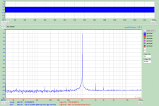
First is loopback at 1V
Thanks for these measurements. The loopback measurement shows a THD of -111dB, but the specification states that Analyzer residual THD @1kHz would be "typical -130 dB, < -120 dB @ 0 dBV". How would you interpret this difference.
I already have sound cards (Lynx Hilo and Terratec Phase X24) that can do better than -110dB THD loopback @0 dBV in ARTA, and so the -120dB THD spec is an important element for me.
I am wondering whether it is possible to actually use software to calibrate hardware distortion on a per unit basis.
Sent from my iPhone using Tapatalk
Sent from my iPhone using Tapatalk
@cwtim01
It is loopback measurement with BW 20-70K with THD -111dB.
For BW 20-20K <-115dB from specifications.
It is loopback measurement with BW 20-70K with THD -111dB.
For BW 20-20K <-115dB from specifications.
Hi Jens,
And also a good commercial audio sine wave generator. That's fantastic! I have some HP audio generators that are more than good enough to calibrate your unit, and the HP 34401A I have will allow extremely close calibration. I can keep those things calibrated and transfer the accuracy to the RTX. So self-calibration and performance confirmation is wonderful! Many thanks for allowing this!Calibration is fairly simple and requires only a good voltmeter and a screwdriver.
It is will all equipment. These days this is tending towards a 2 year cycle and probably depends on input attenuator and your reference voltage drift. So depending on your voltage reference, that might determine the calibration cycle. These normally drift the most when new and after a year or so the drift settles down to some lower rate per year. So, worst case calibration will be in the first couple years.Regarding recommendation about how often it should be calibrated, this is still open.
Thanks for these measurements. The loopback measurement shows a THD of -111dB, but the specification states that Analyzer residual THD @1kHz would be "typical -130 dB, < -120 dB @ 0 dBV". How would you interpret this difference.
I already have sound cards (Lynx Hilo and Terratec Phase X24) that can do better than -110dB THD loopback @0 dBV in ARTA, and so the -120dB THD spec is an important element for me.
I am not quite sure what levels Demian used for the loopback measurement. It doesn't look like 1V to me. The level is measured at -2.1dBFS. If the level was 1V I would expect the measured level to be -10dBFS at the 10dBV input setting (or 0dBFS at the 0dBV setting).
I have attached a measurement, where I have an output of 1V (verified with my HP 34401A). The input is set to the 10dBV range, so the level measured is -10dBFS.
In this case I measure a loopback distortion of -124.7dB.
It is generally a good idea to use levels well below 0dBFS when measuring distortion (THD), because the distortion of the ADC (AK5394A) does increase when approaching full scale.
You refer to the Analyzer residual THD @1kHz, which would be "typical -130 dB, < -120 dB @ 0 dBV"
This is not the loopback figure, but the analyzer (input) only.
I have attached another measurement, where I used a low distortion oscillator with balanced output to drive the analyzer input. In this case I do see a distortion of around -130dB at a level of 1V.
Jens
Attachments

You refer to the Analyzer residual THD @1kHz, which would be "typical -130 dB, < -120 dB @ 0 dBV"
This is not the loopback figure, but the analyzer (input) only.
I have attached another measurement, where I used a low distortion oscillator with balanced output to drive the analyzer input. In this case I do see a distortion of around -130dB at a level of 1V.
Good point! It is easy (for me anyway) to forget that in loopback the total distortion is the distortion of the analyzer plus the distortion of the generator. Hence Victor oscillators. 🙂
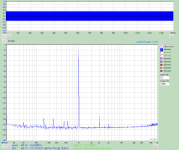
60hz power supply hum and resulting series of distortion frequencies
Hello All,
It appears that the first plot in 1audio’s post #990 is much more telling. It better represents how this instrument will be applied. The only thing missing is the DUT placed between the function generator and the input.
We are not going to apply this instrument with its input only or with some high quality standalone oscillator. I am concerned about the presence of the 60hz power supply hum and resulting series of distortion frequencies in the loopback configuration. The 2Khz and 3Khz spikes are very much like those seen in the AP or Keysight U8903B analyzers.
JensH, please show us an audio Tester loopback with a -10dBV signal applied.
DT
Here is a loopback measurement with an output of -10dBV.
Output attenuator set to 0dBV range
Input attenuator set to 0dBV range
Output to DAC = -10dBFS
48 kHz sample rate
The settings in the loopback plot in post #1005 were:
Output attenuator set to 20dBV range
Input attenuator set to 10dBV range
Output to DAC = -20dBFS
192 kHz sample rate (does not make much difference)
Changing from -20dBFS in the previous plot to -10dBFS increases the distortion of the DAC.
The 50/60 Hz hum can be a challlenge, especially when using unbalanced connections. Using the balanced inputs and proper cables will normally keep the noise at an acceptable level.
I agree that using a very low distortion standalone oscillator should not be necessary in most cases. In this case it was used to separate the issues, so that only the distortion of the analyzer was measured. With a loopback connection, and no other reference, you don't know if the distortion you see is caused by the generator or the analyzer.
Using a 1kHz notch filter I recently measured the distortion of the "Low Distortion Oscillator" to be well below the limits of the analyzer input/ADC.
Attachments
Regarding the power line hum. It is probably to late for such additions, but how about providing the possibility of an alternative supply power (e.g. battery) by the user.
Easiest would perhaps be a switch cutting the secondary AC and switch the input of the regulated supply to some external connectors, where the user can supply the necessary.
Easiest would perhaps be a switch cutting the secondary AC and switch the input of the regulated supply to some external connectors, where the user can supply the necessary.
Jens, two questions
1.) what is the allowed DC offset when measuring AC cupeled?
E.g. Analyzer in 100mv range, AC cupeled, single ended input, measuring the noise of DC supply, how much DC voltage would be allowed?
2.) what is the allowed common mode voltage when measuring balanced.
E.g. measuring the difference the source (at + ballanced) and the output of a unity gain buffer (at - ballanced) in 100mv range, what would the allowed pp-voltage of signal?
1) The input capacitors are 250V, but it would probably be wise to stay below 150V DC.
2) For input ranges of 10dBV or below, it should be safe if the common mode voltage + signal voltage is below 10dBV. At the 10dBV range and below there will be a hard limiting function at around +/- 9 V peak. Some distortion may be seen when approaching these limits.
At input ranges of 20dBV and above the common mode voltage can be higher, since the signal and the common mode voltage will be attenuated.
The power consumption is probably a bit at the high end for battery supply. And I think that in almost all cases the built-in supply will be quiet enough.
What did you do with the National parts?
Just out of interest - what did you end up with regarding the opamp/buffers? have you bought a lifetime supply of the LME49990's or did you go with one of the other you mentioned ? (OPA1611, MAX9632, ADA4898-1, AD797)
Just out of interest - what did you end up with regarding the opamp/buffers? have you bought a lifetime supply of the LME49990's or did you go with one of the other you mentioned ? (OPA1611, MAX9632, ADA4898-1, AD797)
So far I stick to the LME49990. We have a reasonable quantity in stock.
One day I may have to change it though. Probably to the AD797 or MAX9632. Or perhaps different IC's in different positions.
One day I may have to change it though. Probably to the AD797 or MAX9632. Or perhaps different IC's in different positions.
OK, just checked the Maxim web page. The MAX9632 now has the status "Last Time Buy"🙁
So not really an option anymore.
So not really an option anymore.
Yes. At least in the early tests it did not perform as well as the LME49990, AD797 and MAX9632. I only tested them in the input amplifier, where it is working with the LSK389 in front. I did not test it in the other positions. I only had a few available.
Input output connections question:
Are the GND pins of the input and output XLR (and BNC) all connected together?
The reason for my question is that I have in the past found it impossible to measure amps with balanced inputs and floating (SE) output with a single sound card as the common GND effectively "un-floats" the output of the amp.
If not: any known workaround for this problem?
Tak,
Nicolai
Yes, the ground pins are all connected together.
If you have an amplifier with a balanced input and unbalanced (single ended) output:
Connect the input of the amp with a normal balanced connection to the generator output.
Connect the output to the + input of the analyzer and the ground from the amplifier output to the - input of the analyzer.
So, use either figure 5e, 5f or 5g from this Grounding and Shielding Audio Devices.
Jens IIRC your SE output is between one of the BAL output phases and Gnd. This is risky, as it introduces Gnd as a ref for the SE signal.
The low noise way to do this is with a BAL to SE stage taking the TWO BAL outputs as inputs and outputs the difference as a SE output signal. That way the SE output signal is build without Gnd trying to budge in. IOW, instead of using Gnd as a ref, use the other phase as the ref. It has the additional advantage that it preserves the signal level - the BAL and SE signals are now equal.
NOW you can use a convenient Gnd point as a ref for the SE output connector.
Jan
Last edited:
- Home
- Design & Build
- Equipment & Tools
- DIY Audio Analyzer with AK5397/AK5394A and AK4490