I had the same hope. But the roll off at high sample rates is shown clearly in figure 6 and 7 in the AK5397 data sheet.
It may still be useful, although with some limitations. And it may require an additional low pass filter, since the attenuation above half the sample rate is not very good.
It may still be useful, although with some limitations. And it may require an additional low pass filter, since the attenuation above half the sample rate is not very good.
I got the AK5394A add-on boards back a few days ago. One board has been mounted. I have connected it to the main PCB using one analog input channel to feed one ADC input. The other analog input channel is still connected to the AK5397, which is quite convenient, because I can use both converters simultaneously, making it easy to compare the performance.
I have modified one ADC driver to fit with the AK5394A. The total gain had to be changed a little (around 1.3dB) to get the same sensitivity on the AK5394A channel and the AK5397 channel. The difference is less than 0.1dB.
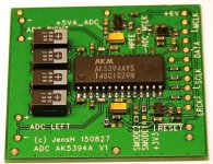
I have attached a picture of the AK5394A board and some measurement results. All the measurements shown are at 192kHz sample rate. The red (right channel) is the AK5397.
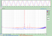
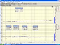
Distortion: The AK5394A is a clear winner! With an input signal of -1dBFS I measured THD at around -101dB for the AK5397 and -125 to -127dB for the AK5394A! To get to the results of -125 to -127dB I had to cool the AK5394A a little. When left running for around 30min the distortion increased to around -119dB. Not quite as muxh as what I saw on my older AK5394A design. This may be due to the fact that the AK5394A add-on board is mounted vertically and therefore gets more natural cooling than the older design, which was a flat design.
The ADC temperature clearly changes the 3rd and 5th harmonics. The 2nd harmonic is almost constant when changing the temperature.
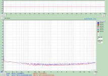
Idle noise: The new AK5397 wins by just over 3dB, which was expected. The measurement was done with a 150ohm resistor across each input, set to the 3V range. The noise level was measured over a 20kHz bandwidth.
While the idle noise is low on the AK5397, the noise increases quite a lot when high signals levels are input. See the last figure.
The noise at the upper end is from the generator (AK4490). It depends on the output level. It disappears at high levels, but then the distortion increases.
To rule out differences in the two channels of the generator, I also tried swapping the leads. This made no difference. I also tried the Stanford Research DS360. The results were almost the same, but I could not quite reach the -126 to -127dB distortion. Around -125dB was the best result I saw.
So the preliminary conclusion is that for this design I need to go back to the AK5394A. Perhaps with some temperature control to get the best performance.
This means a farewell to the sample rates above 192kHz, but if the choice is between THD of -101 and -125, this is a small sacrifice.
I have modified one ADC driver to fit with the AK5394A. The total gain had to be changed a little (around 1.3dB) to get the same sensitivity on the AK5394A channel and the AK5397 channel. The difference is less than 0.1dB.
I have attached a picture of the AK5394A board and some measurement results. All the measurements shown are at 192kHz sample rate. The red (right channel) is the AK5397.
Distortion: The AK5394A is a clear winner! With an input signal of -1dBFS I measured THD at around -101dB for the AK5397 and -125 to -127dB for the AK5394A! To get to the results of -125 to -127dB I had to cool the AK5394A a little. When left running for around 30min the distortion increased to around -119dB. Not quite as muxh as what I saw on my older AK5394A design. This may be due to the fact that the AK5394A add-on board is mounted vertically and therefore gets more natural cooling than the older design, which was a flat design.
The ADC temperature clearly changes the 3rd and 5th harmonics. The 2nd harmonic is almost constant when changing the temperature.
Idle noise: The new AK5397 wins by just over 3dB, which was expected. The measurement was done with a 150ohm resistor across each input, set to the 3V range. The noise level was measured over a 20kHz bandwidth.
While the idle noise is low on the AK5397, the noise increases quite a lot when high signals levels are input. See the last figure.
The noise at the upper end is from the generator (AK4490). It depends on the output level. It disappears at high levels, but then the distortion increases.
To rule out differences in the two channels of the generator, I also tried swapping the leads. This made no difference. I also tried the Stanford Research DS360. The results were almost the same, but I could not quite reach the -126 to -127dB distortion. Around -125dB was the best result I saw.
So the preliminary conclusion is that for this design I need to go back to the AK5394A. Perhaps with some temperature control to get the best performance.
This means a farewell to the sample rates above 192kHz, but if the choice is between THD of -101 and -125, this is a small sacrifice.
Attachments
-
 AK5394A PCB_150913.jpg186 KB · Views: 1,291
 -
 Idle noise_150ohm across each input_AK5394A left_AK5397 right_input 3V range_128k FFT_average ov.png36.6 KB · Views: 1,115
 -
 1kHz distortion_AK5394A channel_-11.4dBFS out from AK4490_input 3V range_128k FFT_average over 1.png36.3 KB · Views: 1,062
 -
 1kHz distortion_AK5394A left cooled by blowing with a straw_AK5397 right_-11.4dBFS out from AK44.png41.1 KB · Views: 1,110
I have attached a picture of the AK5394A board and some measurement results. All the measurements shown are at 192kHz sample rate. The red (right channel) is the AK5397.
Distortion: The AK5394A is a clear winner!
So the preliminary conclusion is that for this design I need to go back to the AK5394A. Perhaps with some temperature control to get the best performance.
This means a farewell to the sample rates above 192kHz, but if the choice is between THD of -101 and -125, this is a small sacrifice.
😎🙂
THx-RNMarsh
Dear JensH,
Hats off, you are doing really nice experiments here. Thanks for all the efforts and money of yours invested..
Hats off, you are doing really nice experiments here. Thanks for all the efforts and money of yours invested..

Yes, there is definitely some noise from the power supply. Could be magnetically coupled or coupled due to the layout.
But apart from the 50Hz and harmonics there is some additional noise, with a distance of around 10Hz. This looks a bit strange.
Once you add some gain to the input there will probably be even more noise. In my measurement I set the input to the 3V range, which means that the gain is around 12dB higher than it is in your input circuit. It takes a careful circuit design and layout to optimize the noise performance.
I don't think that the temperature influences the noise floor in any significant way (except for the usual thermal noise of course). I have seen a much larger influence on the distortion.
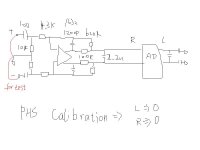
If you connect the inputs of the ADC directly to ground the ADC will not really work and you the output is meaningless. I assume that you have a 2.5V reference voltage on the OPA1632 although it is not shown in your schematic.
But apart from the 50Hz and harmonics there is some additional noise, with a distance of around 10Hz. This looks a bit strange.
Once you add some gain to the input there will probably be even more noise. In my measurement I set the input to the 3V range, which means that the gain is around 12dB higher than it is in your input circuit. It takes a careful circuit design and layout to optimize the noise performance.
I don't think that the temperature influences the noise floor in any significant way (except for the usual thermal noise of course). I have seen a much larger influence on the distortion.
If you connect the inputs of the ADC directly to ground the ADC will not really work and you the output is meaningless. I assume that you have a 2.5V reference voltage on the OPA1632 although it is not shown in your schematic.
Hi Jens,
Many thanks for sharing your testing and development progress.
Does AK5394A hold the same advantage over AK5397 at other frequencies? I'm thinking 10 kHz or so.
Many thanks for sharing your testing and development progress.
Does AK5394A hold the same advantage over AK5397 at other frequencies? I'm thinking 10 kHz or so.
It seems to be a general picture. I just checked it. With a level of -1dBFS I measured distortions of -100.3dB for the AK5397 and -112dB for the AK5394A.
Jens:
Your results look a lot like I was getting from the AK5394A demo board. Once I find the demo board I'll check for any other tricks on it that may be applicable. Excellent work.
I had never noticed the temperature sensitivity but I was not looking and just attributed differences over time to "gremlins".
This does prod me to figure out how to upgrade the EMU 1616M. And not break it in the process.
It may be possible to add a mixer and local oscillator to the front end to extend the measurement range of the system. That could extend the range to almost anything. I found this reference that has some good fundamentals: http://www.eecs.berkeley.edu/Pubs/TechRpts/2009/EECS-2009-81.pdf but is pretty heavy going.
Another, possibly more useful, extension is to parallel multiple ADC's. AKM's apps guy first suggested this to me. You need a DSP that can run at 192KHz, not too difficult, and then its a simple mixer. 4 ADC's, 2 chips per channel could give a 6 dB improvement in SNR. In practice probably less but still a significant improvement. If you are using a minidsp for the USB interface it may be able to handle the task. This would be a good argument for modularizing the ADC's.
That is definitely a way to get a lower noise. I have used this method in some product designs based on the CS5361 to get a good dynamic range at a reasonable power consumption (and cost).
It will of course increase the cost. To make it in an optimum way also the ADC drivers should be doubled/quadrupled. I have seen with one ADC that it didn't like having the two inputs coupled directly in parallel. Or perhaps it was the ADC driver? If the ADC driver is common, the noise of the ADC driver will not be reduced as it would when using 2 or 4 of them.
And the question is also: how much dynamic range do we actually need? If very low noise levels must be measured it is possible to increase the gain of the analog input stage, provided that there is no strong signal at the same time of course. In this case the noise of the input stage will dominate and the noise of the ADC becomes less important.
So, how much dynamic range do we need and why?
Has anyone thought about integrating an active Twin-T notch filter? I am not sure about the distortion of the active version of the filter but it should relax the requirements on the ADC quite a bit.
I have of course thought about it. But have so far decided not to include it. I wanted to keep it (relatively) simple. By adding a tunable low pass filter on the output and a tunable notch filter on the input, the distortion performance could definitely be improved.
thanks for THx-RNMarsh , JensH .
MY PSU is 78xx/79xx , Vref is 10K+10K+100uf from AK5394 AVCC 5V .
I will build another PSU and check the " GND "
MY PSU is 78xx/79xx , Vref is 10K+10K+100uf from AK5394 AVCC 5V .
I will build another PSU and check the " GND "
Another, possibly more useful, extension is to parallel multiple ADC's. AKM's apps guy first suggested this to me. You need a DSP that can run at 192KHz, not too difficult, and then its a simple mixer. 4 ADC's, 2 chips per channel could give a 6 dB improvement in SNR. In practice probably less but still a significant improvement. If you are using a minidsp for the USB interface it may be able to handle the task. This would be a good argument for modularizing the ADC's.
Simple to use the AK5388 (4 Channels) and simple connect it as dual mono.
Coding DSP rises the project to never ending

just my

Hp
HpW said:Coding DSP rises the project to never ending
Well, I don't necessarily think so. Given Jens's "track record" until now, he seems to get the job done. That being said, I think Jens would be more likely to use an FPGA.
We will have to wait to see what Jens comes up with.
Mogens
I am not sure that a single AK5388 will bring any advantages compared to a single AK5394A. In mono mode it may give two channels with a dynamic range of 123dB, which is what we have got already with the AK5394A.
And there is yet again some unknown performance metrics.
It seems like the AK5388 has a large increase in noise at high frequencies, see the Evaluation Board manual figure 25 and 26.
And there is yet again some unknown performance metrics.
It seems like the AK5388 has a large increase in noise at high frequencies, see the Evaluation Board manual figure 25 and 26.
It isnt so much the dynamic range..... as it is the accuracy below -100dB. This is where a tunable - an hopefully integrated-- notch filter is needed. For the harmonic accuracy below -100dB.
So far IC converters have not been accurate for harmonic analysis at low harm. levels without the notch filter. Note their use in commercial analyzers (better than +/- 1dB of measured/indicated harmonic level for 2-5th harmonic).
THx-RNMarsh
So far IC converters have not been accurate for harmonic analysis at low harm. levels without the notch filter. Note their use in commercial analyzers (better than +/- 1dB of measured/indicated harmonic level for 2-5th harmonic).
THx-RNMarsh
Last edited:
- Home
- Design & Build
- Equipment & Tools
- DIY Audio Analyzer with AK5397/AK5394A and AK4490