I have an Emu 1820m which has several AK5394A inside, but they suffer from a few issues. One is that all of the big electrolytic caps go bad, they are either bad caps or aren't up to the temperatures and ripple currents they are exposed to. I recapped the whole thing and it works fine. I used solid polymer caps with very high temp and ripple current ratings at the switcher output. The heat is an issue, the foam gaskets in the two units I have seen end up discolored from the heat it looks like!
I haven't been using it for the inputs, so I run it open without the ADC board connected and the driver doesn't even complain.
I haven't been using it for the inputs, so I run it open without the ADC board connected and the driver doesn't even complain.
The 1616 is a denser design and needs both boards to function. I think the power supply is on a different board from the FPGA.
see QA405. Going to use the AK parts. Prototyping stage. Cost? Higher.
https://www.quantasylum.com/content/Home/tabid/40/EntryId/33/QA405.aspx#Comments
THx-RNMarsh
https://www.quantasylum.com/content/Home/tabid/40/EntryId/33/QA405.aspx#Comments
THx-RNMarsh
Keep us posted on the QA405 RNMarsh
Liked your paper on interface intermodulation distortion.
As Otala has found the good old emitter follower is best !!
Liked your paper on interface intermodulation distortion.
As Otala has found the good old emitter follower is best !!
I have just made some measurements on the new AK5397 based design for comparison.
Just to continue on the meaning of the based thread..
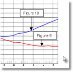
Your given graph from the AK5397 looks like as from AK9394A datasheet (blue line Figure10) on page 21 figure 11 ....
In other words: Is this a question of the used input circuit???
Hp
Attachments
Last edited:
I don't think so. But I will need to verify it.
I think that the difference between figure 9 and figure 10 is the common mode distortion of the 5534 in figure 10. The noise level of that circuit is lower than the noise in figure 9 though, which probably explains why the lines are crossing at approximately -13.5dBr.
A have designed a small PCB with the AK5394A + discretes, a couple of voltage regulators and a divide by two circuit for the clock (to get 12.288MHz instead of 24.576MHz). I expect to receive it in around two weeks from now. I plan to disconnect the AK5397 on the main board and connect the AK5394A board instead.
In the meantime I will take a closer look at the generator section.
Just to continue on the meaning of the based thread..
Your given graph from the AK5397 looks like as from AK9394A datasheet (blue line Figure10) on page 21 figure 11 ....
In other words: Is this a question of the used input circuit???
Hp
I believe that there is a typo above. The datasheet appears to be for the AK5394A not AK9394A (appears to be non-existent).
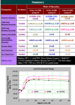
The page 21 graph seems to resemble the test results (lower graph) I published about a decade ago for the LynxTWO which appears to be based on OP275 op amps.
The interesting question for me is: "What is the difference?" No question that there is one, but...
Attachments
I believe that there is a typo above.
I am very sorry..

The interesting question for me is: "What is the difference?" No question that there is one, but...
Reading the latest AK5394AVS.pdf
Just compare the measurement for figure 9 & 10 (page 19/20) and also compare the used ADC driver circuit..
they are not equal 😀 and still using the old 5534 😱
On Page 21 are the measurement figures regarding figure 9 & 10
Hp
Attachments
I am very sorry..
they are not equal 😀 and
of course they are not equal, but to me the question remains how and why they are unequal.
still using the old 5534 😱
Not exactly the case - the schematics clearly show the use of the NJM5534 which is alleged by many to be a significantly improved device.
Ditto for the NJM5532.
of course they are not equal, but to me the question remains how and why they are unequal.
As I wrote earlier:
I think that the difference between figure 9 and figure 10 is the common mode distortion of the 5534 in figure 10. The noise level of that circuit is lower than the noise in figure 9 though, which probably explains why the lines are crossing at approximately -13.5dBr.
If we assume that the NJM5534 is equal to e.g. the NE5534, then this could be the explanation.
The common mode distortion of the OP275 is not impressive either. But since I don't know the schematics of the Lynx it is difficult to say whether this is of any importance in this case.
See Samuel Groners excellent paper "Operational Amplifier Distortion".
Unfortunately the LME49990 is not included in his paper.
As I wrote earlier:
If we assume that the NJM5534 is equal to e.g. the NE5534, then this could be the explanation.
Why is it reasonable to assume that the JRC are baldly lying when they claim that the NJM5532/5532 are improved over the NE5532/NE5534?
http://www.njr.com/semicon/PDF/NJM5532_E.pdf
The NJM parts are widely used, is low cost the only reason why?
I have not assumed that they are lying.
But in the data sheet they don't claim that the NJM5532 is improved over the NE5532. What they do claim is that it is superior to the NJM1458, which is definitely no surprise. The NJM1458 has a performance similar to an NJM741, which looks like a part equivalent to the LM741.
You can get better parts today, but used correctly the 5532/34 parts gives good value for money. So I definitely think that cost is the main reason for using them.
I have not used them myself, but I have used the NJM2068, which also gives a good performance at a very low cost.
I have now looked a bit closer at the generator section.
Some time ago I saw a strange phenomenon. When the output attenuator was set to direct output, with no attenuation, the distortion looked fine. But if I attenuated the signal by 20 or 40dB the distortion increased dramatically.
It turned out that the output drivers were oscillating (at around 80MHz), but only when attenuation was used. The load is almost the same in all cases, but apparently the small change in load (from the attached wire) was enough to stop the oscillation when no attenuation was used.
The output drivers are based on LME49990 buffered by LME49600. They are connected as standard differential amplifiers, with 4 x 1.27k resistors. I had used 2 x 22pF also, one across the feedback resistor and one to ground in an attempt to make it stable. But it turned out that I had to remove these capacitors and set the LME49600 to high bandwidth to make it stable. Today I tried to increase the values to 47pF, but it was still unstable, so I had to remove them again.
Once the output drivers got stable the huge distortion increase disappeared.
I wonder if another op-amp may actually be better for this circuit? Perhaps the wide bandwidth of the LME49990 (110MHz) combined with the peak in the frequency response of the LME49600 at around 100MHz is asking for trouble? Perhaps an LME49710 or an OPA1611 would be better?
Does anyone here have any experience with that?
Tonight I repeated the measurements of distortion versus level shown in post #48. The results were very similar. So it was not caused by the instability.
I then measured the distortion at 48, 96 and 192kHz sample rates at a level of -12dBFS using the VP7722A. -12dBFS is close to the distortion minimum seen on the 96 and 192kHz plots. With this method the distortion was very similar, at 0.00007% (reading was around -122dB when selecting dB output). Measured as THD with 400Hz HP and 80kHz LP filters.
Measured at -12dBFS, using a loop-back connection and audioTester, I got distortion levels of -119.4, -118.6 and -117.8dB for 48, 96 and 192kHz respectively. I assume that the differences between the VP7722A results and these results are due to the ADC and the input stage.
So the measurements using Steps are still a bit strange. I am new to Steps, so perhaps there are some settings that I need to change?
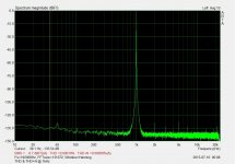
In an attempt to determine if the distortion seen at high levels with the AK5397 I made some additional tests today.
I used the generator section to generate a 1kHz signal. Output level was -11.4dBFS. The generator output attenuator was set to give no attenuation. The input attenuator was set to the 3V range. With a loop-back connection I got a level from the ADC of -1dBFS.
The distortion was measured using audioTester and it showed -99.2dB.
I then used a VP7722A to measure the distortion at different points (single ended). Referring to figure 41 in the data sheet for the AK5397 this was before and after the 5 ohm resistors on the ADC inputs (4.7ohm in my case).
The results were quite interesting.
Before the resistors I measured around -121dB distortion on average for the four signals. I measured from -119 to -122. The readings from the VP7722A were flickering somewhat, so these are "averaged" values.
After the resistors the distortion was a little bit higher, around -118dB on average.
These values are far better than the values seen on the ADC output. I think that this points towards the ADC as the cause of the distortion, not the input stages.
The AK5394A add-on boards are on their way from the far east PCB manufacturer. They should be here in a week from now.
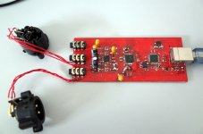
Here is a ugly little adc from me to measure my daily task.
THS4532 1 x
PCM4222 fixed 48khz
SA9027 UAC1.0 fixed 48khz
No isolation
1.2Vrms input at 0dBFS.
Zin a bit low (considering the source signal meet the INres-FBres-opamp output) 😱
No another opamp to drive Vcom
Down side
Reading fluctuate every few tenth seconds, no idea why
Reading take from
FW Compensated ES9018AQ2M, OPA1632 I/V, OPA1632 Buffer.
P/S, i am waiting QA405 to replace my test bed too.
Attachments
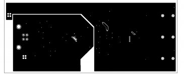
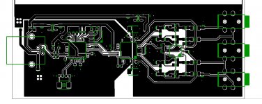
Here is little things i realized during prototypes.
Separated ground plane returns to one starground yield better results, better than pouring one whole even undisturbed ground plane for a board.
Ferrite beads for terminating digital ground plane & Vbus
Inductor for terminating analog ground plane & Vbus.
Might be helpful might be not, I have no proof in this, but at least doing all this make my ADC measure better.
Attachments
The distortion was measured using audioTester and it showed -99.2dB.
Well, this are the same figures as the AK5397 evaluation board and far away from the data sheet! 😱 But they used a different op-amp & circuit to get into this -108 figures.
Funny is that the evaluation board AK5388 & op-amps (NJM5534d) gets on some channels even better figures 😕
Hp
Last edited:
I have now looked a bit closer at the generator section.
Some time ago I saw a strange phenomenon. When the output attenuator was set to direct output, with no attenuation, the distortion looked fine. But if I attenuated the signal by 20 or 40dB the distortion increased dramatically.
It turned out that the output drivers were oscillating (at around 80MHz), but only when attenuation was used. The load is almost the same in all cases, but apparently the small change in load (from the attached wire) was enough to stop the oscillation when no attenuation was used.
The output drivers are based on LME49990 buffered by LME49600. They are connected as standard differential amplifiers, with 4 x 1.27k resistors. I had used 2 x 22pF also, one across the feedback resistor and one to ground in an attempt to make it stable. But it turned out that I had to remove these capacitors and set the LME49600 to high bandwidth to make it stable. Today I tried to increase the values to 47pF, but it was still unstable, so I had to remove them again.
Once the output drivers got stable the huge distortion increase disappeared.
I wonder if another op-amp may actually be better for this circuit? Perhaps the wide bandwidth of the LME49990 (110MHz) combined with the peak in the frequency response of the LME49600 at around 100MHz is asking for trouble? Perhaps an LME49710 or an OPA1611 would be better?
Does anyone here have any experience with that?
Take a look at this : http://www.ti.com/lit/ds/symlink/buf634.pdf
Look for the "Boosting Op Amp Output Current" paragraph on page 8 and look at figure 4 on page 9.
BUF634 is an older high speed buffer but with features comparable with the never more modern LME49600.
Using a very high speed opamp like the LME49990 with a LME49600 running in low BW mode within its feedback loop could lead to trouble, as you found out.
Even with other opamps, like the LME49710 with a 55MHz bandwidth or OPA1611 with 40MHz bandwidth you should still be running the LME49600 in wide BW mode.
Regards,
Christian
Last edited:
I had seen the figure you are referring to. I also simulated it some time ago. But I haven't actually tried it.
In the simulation I got a large peak at 23MHz if I used a 200pF capacitor for C1 in figure 4 (simulated with an LME49600). But perhaps it works fine in the real world? At least the configuration I tried with 22pF or 47pF from the output of the LME49600 simulated fine, but performed poorly, oscillating under certain conditions.
In the simulation I got a large peak at 23MHz if I used a 200pF capacitor for C1 in figure 4 (simulated with an LME49600). But perhaps it works fine in the real world? At least the configuration I tried with 22pF or 47pF from the output of the LME49600 simulated fine, but performed poorly, oscillating under certain conditions.
of course they are not equal, but to me the question remains how and why they are unequal.
Not exactly the case - the schematics clearly show the use of the NJM5534 which is alleged by many to be a significantly improved device.
Ditto for the NJM5532.
I have done a lot of tweaking to the AKD5394A board to improve its performance. I think I posted some of the info at some point. I have lost track of it but I will find it.
Swapping the opamps to LME49710s makes a big difference but you need to use an external master clock first. The on board oscillator is a posterchild for what not to do.
I was hoping the AK4397 would be as good with the additional bandwidth. AKM told me that it still rolls off around 100 KHz even in higher sample rates.
- Home
- Design & Build
- Equipment & Tools
- DIY Audio Analyzer with AK5397/AK5394A and AK4490