Hi Alex,
Thanks.
That is definitely some fairly low supply voltages. But it seems to work well.
Have you looked at what influence the 3k resistors have on the performance? Do you have any references to litterature about this?
Thanks.
That is definitely some fairly low supply voltages. But it seems to work well.
Have you looked at what influence the 3k resistors have on the performance? Do you have any references to litterature about this?
Hi Alex,
Thanks.
That is definitely some fairly low supply voltages. But it seems to work well.
Low voltages, because I want to power it from the 12V battery (which can drop to 10.5-11v).
Better to use +5V/0V power, in this way we do not need any overvoltage protection at the ADC's inputs (I used 4 shottky diodes), but not with OPA1632 (it is not rail-to-rail and at 0dBFS signal klipping occures). Maybe with THS4521.
Have you looked at what influence the 3k resistors have on the performance?
Yes, but lost the measurements with the old hard disc 🙁
These resistors influence to the 2nd and 3rd harmonisc height - one rises a little bit, and second falls, but I don;t remember which one.
Do you have any references to litterature about this?
I have seen this solution in application note for ARDA's ADC AT1201 (AT1201 AN 1.pdf).
BTW, somebody used this ADC?
More then a year ago I make the test PCB, but maybe layout was not good, or something else, but I don't obtained good results -THD was higher then expected ann the noise floor was higher.
This was one of the reasons, why I use AK5394 - I checked AT1201 and PCM4222 before, with the same input circuit, and 5394 was the best.
I have seen this solution in application note for ARDA's ADC AT1201 (AT1201 AN 1.pdf).
I have also seen this, but there is no explanation regarding the benefit of using these resistors.
My layout for the AK5394A based design is actually prepared for these resistors, so it will be easy to check if it makes any difference. I just never mounted them.
ARDA also seems to use small values for the feedback resistors, like I do at the moment.
With the USB streamer I am limited to 192kHz.
Hmm, not really while the streamer as 8 I/O channels and those can be used with channel bundling for 2x, 4x stereo or 8x mono speed of the base sample rate as 192kHz.
I implemented already those using the ASIO interface where you could have 1x on output and 2x,4x8x on the input using the same sample rate.
Required is a custom HW solution how does the channel I2S bundling and un bundling for the I/O... see picture 4x stereo as 768kHz using local loop-back (as jumpers on the USBStreamer) ... Jens already know this 😀
Hp
Attachments
ARDA also seems to use small values for the feedback resistors, like I do at the moment.
Usually, resistor values is the trade off between THD and SNR, as I was more interesting in lower THD then SND, I used the higher values.
Also because I do not se additional input buffer, I want to keep thw input impedance as high as possible - to be able to measure various circuits, which THD is rising if thee load is less then 1-2k.
Yes, unfortunately nothing comes for free!
I tried to add two 3k3 resistors from the OPA1632 outputs to the negative supply (-15V). It didn't really change the distortion. After that I changed the two 267ohm feedback resistors to 1k27. That didn't change the distortion either. I have used a single ended source (VP7722A) into an instrumentation amplifier (OPA1612) preceding the OPA1632.
I am almost running out of ideas to try. Tomorrow I plan to try a Stanford Research DS360 as source to get a balanced source, just to check if that makes a difference.
Yes, unfortunately nothing comes for free!
I tried to add two 3k3 resistors from the OPA1632 outputs to the negative supply (-15V). It didn't really change the distortion. After that I changed the two 267ohm feedback resistors to 1k27. That didn't change the distortion either. I have used a single ended source (VP7722A) into an instrumentation amplifier (OPA1612) preceding the OPA1632.
I am almost running out of ideas to try. Tomorrow I plan to try a Stanford Research DS360 as source to get a balanced source, just to check if that makes a difference.
What about lowering the output hf impedance which the adc look into.
By simple means of an rc lowpass filter c0g/np0 capacitor In the range of 1 - 10nF!?
Ok, sounds good. I would Maybe try the circuit In figure 11 In the datasheet of the opamp.
But with the distortion level of the opamp and with good decoupling i would start looking somewhere else. Reference voltage or source as the source impedance driving opa1632 should be able to drive with very low thd into low ohmic loads.
Sent from my iPhone using Tapatalk
But with the distortion level of the opamp and with good decoupling i would start looking somewhere else. Reference voltage or source as the source impedance driving opa1632 should be able to drive with very low thd into low ohmic loads.
Sent from my iPhone using Tapatalk
On the AK5394A I have a 2.2nF NP0 across each of the inputs.
You use 2 caps from adc's inputs to ground, instead of one differential, or you mean "each input" = 2 channels?
We have to give Jens credit for the pcb layout. Normally i am hard to impress but i like it.
Sent from my iPhone using Tapatalk
Sent from my iPhone using Tapatalk
Thanks for your kind words 🙂
@altor,
I use one differential for the left channel and one differential for the right channel.
@altor,
I use one differential for the left channel and one differential for the right channel.
Originally posted by sonnya:
But with the distortion level of the opamp and with good decoupling i would start looking somewhere else. Reference voltage or source as the source impedance driving opa1632 should be able to drive with very low thd into low ohmic loads.
And thanks for the tip 🙂
I took a look at the design around the AK5394A. I had made an alternative design around the decoupling of the VREFL+, VREFL-, VREFR+ and VREFR-. That turned out not to be a good idea. I have now added 4 x 330uF/10V tantalum caps on these four reference voltages. And this gives a huge increase in the performance.
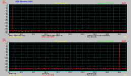
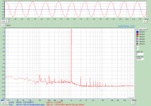
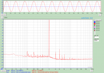
I have shown two measurements below. The best result I have seen until now was on an input with just an OPA1632, connected through 2 x 1000uF/25V capacitors to the generator (DS360). The THD at a sample frequency of 192 kHz and a level of -0.32dBFS is -119.6dB. BUT: it changes over time (temperature)! I noticed that the distortion seemed to increase over time. I then tried to cool the ADC by blowing on it and the distortion dropped again. After around 5 minutes of warming up the distortion has increased to around -108dB. This is shown in the second figure.
At initial power-ON the distortion is even higher (above -100dB). It then drops and finally increases again 😕
It seems like it is primarily the third harmonic that changes with the temperature.
Has anyone else seen such a strong temperature dependence with the AK5394A?
Attachments
coupling -- try bipolar caps or non-polar types. 105 degree C, preferably.
Is there a circuitry method to trim distortion and do so when warmed up?
THx-RNMarsh
Is there a circuitry method to trim distortion and do so when warmed up?
THx-RNMarsh
Last edited:
What do you mean by coupling and where?
The 4 x 330uF capacitors are used as reference decoupling capacitors. I could try e.g. normal electrolytic capacitors instead of the tantalums. But they are not getting terribly hot. At the moment they are hanging in the air, connected with short wires.
It seems to be the ADC IC itself, which is temperature sensitive. When I cooled it down, I used a straw, so that only the IC would get any real cooling.
I am not aware of any method to trim the distortion of the AK5394A.
Hello JensH
I know that the 5394A dissipate much power than newer ADC (near to one Watt).
Have you try to glue a small heat-sink on his top to step-down it's temperature and allowed lower THD over the time ?
Frex
I know that the 5394A dissipate much power than newer ADC (near to one Watt).
Have you try to glue a small heat-sink on his top to step-down it's temperature and allowed lower THD over the time ?
Frex
Hi Frex,
Yes, the AK5394A is rather power hungry.
No, I have not tried to use a heat sink. I will try out different capacitors for the decoupling to see if that makes a difference. I think I have some suitable electrolytic capacitors and some OSCON's somewhere in my collection of parts.
But it seems like the ADC should not be too cold either. Just after power ON the distortion is very high. Yesterday I made a test, where it was powered off for maybe an hour. Just after power ON I measured the THD. It was -87.9dB! When warming up it improves to very good levels and then becomes worse again.
If the temperature is the only problem I could mount a Peltier element, a heat sink and a temperature control to optimize the working temperature. But first I need to figure out whether the temperature is the only problem or whether there are other contributing factors as well, perhaps leading to a bad combination.
I was looking on your pcb again
I would replace your tantal decoupling with x5r or x7r capacitor.
And the ones close by the adc or dac with 10nF
It is just a suggestion
I would replace your tantal decoupling with x5r or x7r capacitor.
And the ones close by the adc or dac with 10nF
It is just a suggestion
When looking on the datasheet for the evaluation board, it looks like the distortion you get after warm up is close to the measurements they (akm) Got .
Just a thought . Add an programmable notch filter to enable lower distortion of single tone measurements ....
Then you could add more gain after notch filter to get higher dynamic range..
Sent from my iPhone using Tapatalk
Just a thought . Add an programmable notch filter to enable lower distortion of single tone measurements ....
Then you could add more gain after notch filter to get higher dynamic range..
Sent from my iPhone using Tapatalk
Jens-
Tantalum caps are actually lower noise than Electrolytics if its an issue. Wet slug are best and incredibly expensive. However it should not be an issue. The size will affect distortion, well documented in other parts as i remember.
You are measuring pretty close to FS. A small change in vref (temperature?) could make a big difference. If you measure at -6 do you see the same effect?
I will try to find the AKD5394A board and duplicate your measurements to see if I get similar results.
- Home
- Design & Build
- Equipment & Tools
- DIY Audio Analyzer with AK5397/AK5394A and AK4490