Simple to use the AK5388 (4 Channels) and simple connect it as dual mono.
Better to use 5574 or 5578.
Channel multiplying + downsample can help to reduce the noise floor, or to remain the noise floor and to decrease 0dBFS level to get the lover harms.
But where to get it...
Better to use 5574 or 5578.
Channel multiplying + downsample can help to reduce the noise floor, or to remain the noise floor and to decrease 0dBFS level to get the lover harms..
The point is this: AKM shows marketing without providing real measurements/beef (also above 192kHz SR) and any benefits in THD over the AK5394. Look at the measurements given from Jens ... the current & real results!
My personal voting (Jens already know):
- Have a modular design ADC/DAC
- A main board to use the platform as DIY
- Where you may change any ADC or DAC with different
- Replace the input or output part for your special needs
(noise density or high voltage = tubes measurements)
and have a working USB to I2S acquisition I/O platform using the USBStreamer and Jens isolation board ... and may an additional FPGA for x2, x4 speed (384,768 kHz) operations.
my

Hp
The point is this: AKM shows marketing without providing real measurements/beef (also above 192kHz SR) and any benefits in THD over the AK5394.
Yes, I know, but this is for simple chip using.
I talked about channel paralleling and sample rate down conversion, which increase virtual ENOB and it will be possible to increase SNR OR to keep SNR the same and decrease harmonics (by lowering the voltage level at ADC's input).
Look at the measurements given from Jens ... the current & real results!
I saw, bit I'm also have my own 5394 measurements, you can see above.
and have a working USB to I2S acquisition I/O platform
I'm also have, my own.
Thanks to all for your inputs.
@ RNMarsh
As stated previously I don't have plans to add a tunable notch filter to the design, or at least not the "main design". But I could consider adding some connectors to make it possible to expand the "main board" with a tunable notch filter, and perhaps also a tunable low pass/band pass filter on the generator side. This add-on board could then be mounted over or below the main board.
@1audio
A compromise in terms of increasing the dynamic range could be to use 2 x AK5394A, one for each channel. In this way it would be possible to improve the noise by 2-3dB. At the same time it would increase the channel separation. A single DSP could easily do the required addition. And also provide an overflow indication, which I miss a little on the AK5394A compared to the AK5397. And the overflow indicator could even be per channel, which it is not on the AK5397.
The ADC's, the ADC drivers and the DSP could be mounted on a module. In this way it will be possible to replace if something even better should turn up in the future.
And if this is done I might as well move the DAC to a module as well.
Or I could keep the converters on the main board and just make it easy to disable and replace them with add-on modules. Too many choices 🙂
@altor
Are you sure that the 5574 or 5578 will be a better solution? At the moment the performance is relatively unknown, at least to me.
What do you mean by "But where to get it... "?
@mkc
I would probably use a DSP and not an FPGA.
By the way, does anyone have an answer to my previous question "So, how much dynamic range do we need and why?".
On another topic: Initially I had decided to design the generator for a 20Vrms balanced output and 10Vrms single ended. For some reason (perhaps a brain melt-down) I "only" have 10Vrms balanced at the moment. My question is therefore: Would 20Vrms balanced actually be needed and for what?
If not, I could reduce some supply voltages a bit, making the board run a little cooler.
Jens-
I think you have already accomplished a lot. Its disappointing that the AK5397 is not an improvement over the AK5394a. The lower noise seems to be the benchmark for the pro audio market but its a naive one since its really hard to get near the dynamic range on upstream stages to even approach these converters. For measurement its an issue that can be worked around in many ways and not a real limitation.
The 120 dB harmonic performance is also more than enough to address almost any real audio circuit measurement needs. I'm concerned that more complexity may prevent the project from finishing.
I think the real issues on the output is voltage into 600 Ohms vs. open circuit and whether the balanced output is isolated from ground. The last is really important for systems that will have ground loops and other problems between input and output.
Most audio amps can be driven to clipping with 3V. I use higher voltages for component test etc. going as high at 16V (8V into 600 Ohms) with the Boonton. That's probably way more than necessary for most applications and lower output usually means less distortion.
@altor
Are you sure that the 5574 or 5578 will be a better solution?
I can be sure, just after I solder the chip on PCB and test it 🙂
Just according to datasheets - THD+N=-110dB, the same as 5394.
SNR is 3 dB worse -120dB.
Using 2 channels in parallel SNR increases for 3dB, and should be the same as 5394.
4 channels paralleling - should give 3dB bonus.
Next - 5574/5578 can operate up to 768kHz, so using 4x down sampling to 192kHz (absolute maximum for 5394) we can expect another +3dB bonus.
Totally - 6dB (fot 5578) better SNR then 5394 for the same sample rate.
Or, shifting the 0dB to -6dBFS, reduce THD at the same SNR.
Maybe this chips are not in full production yet, but I didn't find where to buy 5574 and 5578, Mouser/Digikey/Arrow does not have this chips.What do you mean by "But where to get it... "?
I've sent a message to the local distributor (maybe they have some samples?), but still no answer.
Excellent thread and I applaud you for your meticulousness towards this. The results are very impressive, DIYaudio needs more threads like this. 
Thanks to all for your inputs.
@ RNMarsh
As stated previously I don't have plans to add a tunable notch filter to the design, or at least not the "main design". But I could consider adding some connectors to make it possible to expand the "main board" with a tunable notch filter, and perhaps also a tunable low pass/band pass filter on the generator side. This add-on board could then be mounted over or below the main board.
.
That will be helpful for those who need accurate harmonic meaurements below -100dB. I have several commercial distortion analyzers which I have compared the accuracy of the harmonics measured/displayed below -100db with.... ShibaSoku 725D, Panasonic VP 7722A and Audio-Precision 2722. I have not found converter IC to be able to directly measure with ANY accuracy below -100dB without a notch filter. Neither can these commercial analyzers ($$$) without notch filters for measuring below -100dB.
THx-RNMarsh
.
The 120 dB harmonic performance is also more than enough to address almost any real audio circuit measurement needs. I'm concerned that more complexity may prevent the project from finishing.
Making something that was good enough for almost any real audio measurement needs was the initial target. I share the same concern, but adding a few options for future upgrades may be worth while.
I think the real issues on the output is voltage into 600 Ohms vs. open circuit and whether the balanced output is isolated from ground. The last is really important for systems that will have ground loops and other problems between input and output.
At the moment the outputs are not isolated from ground. I will consider that also. It may not be too difficult, but it will require some additional power supply circuits, some digital isolators and perhaps a transformer for the MCLK.
Would it be sufficient to have all the outputs on one separate ground, so that the two balanced and the two single ended outputs share the same ground plane or does each of the two channels need to have a separate ground? The latter will complicate it further.
At the moment the output impedance is 25 ohm single ended and 50 ohm balanced. I have not included other impedance options.
At the low levels the output impedances are even lower, since I connect the attenuator directly to the outputs, when using the -20 dB or -40 dB steps. There are no resistors in series with the attenuator outputs to achieve a 25/50 ohm output impedance. It does give a small advantage in terms of thermal noise at very low levels.
Does anyone see a problem in the non-constant output impedance?
Maybe this chips are not in full production yet, but I didn't find where to buy 5574 and 5578, Mouser/Digikey/Arrow does not have this chips.
According to AKM's website they are scheduled for production in Q1 2016, so I am not surprised that they don't show up at distributors yet.
I have found that having known impedances has been very important when I add esternal networks. I have an RIAA network and an attenuation network both of which interact with the source Z so it is an issue for me. I built these for testing really sensitive circuits (Moving coil inputs) so low impedance at the output and good isolation from ground noise was important.
I have used the self correcting balanced circuit with success. I can dig it up and post it later. It uses feedback to ensure the output voltage follows the output ground, not the generator ground. Max output is limited but may be enough for most applications. The option you mention with optoisolators and transformer coupled clocks may be more complicated, or not. Mostly depends on the power supply.
I have used the self correcting balanced circuit with success. I can dig it up and post it later. It uses feedback to ensure the output voltage follows the output ground, not the generator ground. Max output is limited but may be enough for most applications. The option you mention with optoisolators and transformer coupled clocks may be more complicated, or not. Mostly depends on the power supply.
I have not found converter IC to be able to directly measure with ANY accuracy below -100dB without a notch filter. Neither can these commercial analyzers ($$$) without notch filters for measuring below -100dB.
When it comes to THD+N I'd agree - with the THD component being the issue.
Verifying harmonic accuracy below -100 dB is quite challenging. There are a number of error sources that need to be dealt with. When I was confirming the accuracy of the Shibasoku I had to lash up several different techniques to test its accuracy. Since you need a source with at least 6 dB less signal than you are checking for it becomes really difficult to know that you have a good source. Even passive notch filters can introduce harmonics at the -120 dB level. Mix harmonic phases and you can get 100 % incorrect numbers.
Verifying harmonic accuracy below -100 dB is quite challenging. There are a number of error sources that need to be dealt with. When I was confirming the accuracy of the Shibasoku I had to lash up several different techniques to test its accuracy. Since you need a source with at least 6 dB less signal than you are checking for it becomes really difficult to know that you have a good source. Even passive notch filters can introduce harmonics at the -120 dB level. Mix harmonic phases and you can get 100 % incorrect numbers.
The old uncertainties. Trying to test the test equipment.
I have found that having known impedances has been very important when I add esternal networks. I have an RIAA network and an attenuation network both of which interact with the source Z so it is an issue for me. I built these for testing really sensitive circuits (Moving coil inputs) so low impedance at the output and good isolation from ground noise was important.
I have used the self correcting balanced circuit with success. I can dig it up and post it later. It uses feedback to ensure the output voltage follows the output ground, not the generator ground. Max output is limited but may be enough for most applications. The option you mention with optoisolators and transformer coupled clocks may be more complicated, or not. Mostly depends on the power supply.
So did you mean something like a quasi-floating balanced output, and not a completely isolated output section?
This may also be feasible. But I don't know if it will be possible to maintain stability in all cases. And how to configure it when using an output attenuator?
The output impedance will of course be known. But as described earlier, it changes when switching from 0dB to -20dB or -40dB output attenuation. They can of course be made equal by putting resistors in series with the output relays, but e.g at the -40dB setting the (thermal) noise will be higher due to having 50ohm balanced output impedance instead of around 5ohm.
If constant output impedance is more important than minimum noise, the resistors should of course be added.
Verifying harmonic accuracy below -100 dB is quite challenging. There are a number of error sources that need to be dealt with. When I was confirming the accuracy of the Shibasoku I had to lash up several different techniques to test its accuracy. Since you need a source with at least 6 dB less signal than you are checking for it becomes really difficult to know that you have a good source. Even passive notch filters can introduce harmonics at the -120 dB level. Mix harmonic phases and you can get 100 % incorrect numbers.
yes. shielding and grounding techniques with DUT can become extreme below -100. The point is this --- there is available equip that also uses direct measurement to -100dB OK (QA400 or E-Mu come to mind)....... how would this be any different/better?
THx-RNMarsh
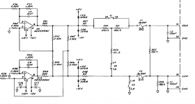
Output circuit suggestion
Below is what I'm suggesting. With buffers it can be scaled to 50 Ohms (but needs plenty of power supply). As long as the difference between grounds is not a lot the output will track the output ground reference. It only needs a handful of resistors and works quite well. You can add a center tap and have an active balanced circuit tracking the load. however you will be limited to around 6-7 volts RMS with a 15 volt supply.
If the difference between the grounds gets too high then you will run into problems but that seems unlikely in this application.
Attachments
Richard:
You seem to be condemning any ADC as being useless below -100 dB. My experience with the AK5394A was that it tracked the Shibasoku 725 quite well given that neither are totally accurate in the -120 dB range. Doing those measurements is quite an exercise since so many things will compromise them. The THD+N measurements are the least useful. Looking for individual harmonics and signals at that level is the only useful aspect. Straight SNR is better done with preamps where getting 150+ dB is not difficult and then the ADC will give useful info on the composition of the noise.
Tuneable notch filters are extremely difficult at -120 dB. Even fixed notch filters are difficult. A passive filter at the input will interact with the DUT in complex ways. You can add a buffer at the input. The Shibasoku is a good one to use but really complex and needs +/- 30V supplies. I don't think an IC input can have enough isolation and low enough input generated distortion to not limit the performance.
Quickly this becomes an exercise in complexity. For most users its already more than good enough for evaluating or troubleshooting virtually any commercial audio design using simple cost effective software like Arta or HPworks.
So far as I am concerned it IS pretty useless below -100dB. Not sure what you mean by Totally accurate..... the 725D is accurate to at least -130. Be happy to measure it for you or anyone. The AP is accurate as well and I could compare with that when you guys have such unit built. Personally, I dont care how hard it is to measure below -100dB accurately.... just that the FFT data being displayed with cheap units in 99% of what is shown isnt accurate data and no one seems to know it isnt unless they have something better for a standard to compare it against.
. I would like to see something which goes to -120dB Accurately. Been a goal of mine for a long time.... to find something cheap that can do it. Maybe this is IT? Will put a lot of commercial instruments out of business if it does.
As you know we can get an old HP339A THD+N analyzer to do better than -100dB (THD+N) with just some parts changes/upgrades and then you can add a notch filter and FFT to it after that. [And, it will do so with up to 300vac input.] We should be able to do much better than that by now.
Hate to be a monster about it... just that to do accurate harmonic analysis below -100dB is Very hard, as you know. I would not want people to think it will be as easy as it appears to be as a PnP unit. The QA400 is PnP and spec are only a few dB better than -100. It may be the price/performance leader to compare against. Can you guys do Much better than that? Will it be linear below -100 to -120dB? And maintain accuracy. We shall see.
THx-RNMarsh
Last edited:
I would suggest as a first step defining accuracy in this context. Is it accurate measurements of the amplitude of the harmonics/IM products? Is it THD+N in a specified bandwidth? What constitutes accuracy? +/- 6 dB, +/- 3 dB, +/- 1 dB? Keep in mind that the closer you get to the noise floor the harder it is to be accurate. Then we can work out methods of verifying the accuracy.
So far as I am concerned it IS pretty useless below -100dB. Not sure what you mean by Totally accurate.....
THx-RNMarsh
I would suggest as a first step defining accuracy in this context..
IMHO suggest to start a new thread as "Accurate measurement below -100 dB"... otherwise it will blow up the current..
My understanding on this is, if the digital domain is accurate as the bit's promise (may also adding dither) .. this will work for the analog (ADC/DAC chain) as well.. 😀
Hp
- Home
- Design & Build
- Equipment & Tools
- DIY Audio Analyzer with AK5397/AK5394A and AK4490