It doesn't really need to know that. It will just measure the differential signal between the two signal lines. If one of them is connected to ground, it will still work and just measure the single ended signal.
I haven't tested the AK5572, so I don't know. It looks reasonably promising though. But at the moment I have no plans to test it. Perhaps later, when I get time for it.
Darn, I've waited so long for an alternative to the expensive analyzers on the market an can't wait any longer, I'm springing for a Prism dscope IIIA. The R&S UP300 didn't fit what I was doing so that one is up for sale. I'll keep this thread on my list because I still want to do a diy unit. Very interesting idea JensH
I know that it has been quiet here for a long time. The project has not been stopped. On the contrary. There has been quite a lot of activity on the project, but there were a lot of details to attend to. I wanted to wait until I had more than just one of the PCB's ready.
I actually got the assembled USB interface, based on an XMOS chip, back from manufacturing early July. Due to the vacation period here, the firmware was not loaded and tested until early August. It went very smooth and the basic functionality is now working very well. Sample rates from 44.1 to 192 kHz is supported with a resolution of 32 bit. There is support for future upgrades with additional channels and it should also be possible to increase the maximum sample rate later on. The I2C monitor/control function has been implemented, but not really tested yet.
I also got the User Interface Board back in July.
I got the ADC and DAC boards back some days ago. Finally, I got the Main Board back late Friday this week. I have tested and adjusted most of them over the weekend and the results are promising.
The only small issue I have noticed so far is a marginal stability of the input amplifier, in some cases only with some gain settings. There is a roughly 12 MHz oscillation in some situations. Hopefully this can be cured by changing a few capacitors to a different value. The LME49990 is a nice op-amp, but it is not always easy to get it stable.
I use the LME49990 in many places in this design. The last buy date is getting close, which is of course another issue. Some of the Main Boards and ADC Boards were assembled without the LME49990. They are intended for testing alternative op-amps. At the moment my candidates are:
OPA1611
MAX9632
ADA4898-1
and perhaps the AD797 (quite expensive and perhaps even more difficult to get stable than the LME49990)
The mechanical parts are lagging behind, so it will still take some time before I have completely assembled units. But it is getting closer as well.
I have attached a few pictures.
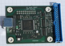
The first picture shows the XMOS-based USB to I2S interface. It is good to finally have my own design, where the isolators are included on the board and additional functionality is relatively easy to implement.
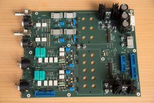
The second picture shows the Main Board without the ADC and DAC Boards.
The last picture shows the Main Board with installed ADC and DAC Boards as well as the User Interface Board.
Regarding availability and pricing I still need to get closer to the final product. I do want to make it available at a fair cost, and perhaps arrange some kind of group buy or similar here on diyaudio. And I keep trying to pull-in the availability date.
I actually got the assembled USB interface, based on an XMOS chip, back from manufacturing early July. Due to the vacation period here, the firmware was not loaded and tested until early August. It went very smooth and the basic functionality is now working very well. Sample rates from 44.1 to 192 kHz is supported with a resolution of 32 bit. There is support for future upgrades with additional channels and it should also be possible to increase the maximum sample rate later on. The I2C monitor/control function has been implemented, but not really tested yet.
I also got the User Interface Board back in July.
I got the ADC and DAC boards back some days ago. Finally, I got the Main Board back late Friday this week. I have tested and adjusted most of them over the weekend and the results are promising.
The only small issue I have noticed so far is a marginal stability of the input amplifier, in some cases only with some gain settings. There is a roughly 12 MHz oscillation in some situations. Hopefully this can be cured by changing a few capacitors to a different value. The LME49990 is a nice op-amp, but it is not always easy to get it stable.
I use the LME49990 in many places in this design. The last buy date is getting close, which is of course another issue. Some of the Main Boards and ADC Boards were assembled without the LME49990. They are intended for testing alternative op-amps. At the moment my candidates are:
OPA1611
MAX9632
ADA4898-1
and perhaps the AD797 (quite expensive and perhaps even more difficult to get stable than the LME49990)
The mechanical parts are lagging behind, so it will still take some time before I have completely assembled units. But it is getting closer as well.
I have attached a few pictures.
The first picture shows the XMOS-based USB to I2S interface. It is good to finally have my own design, where the isolators are included on the board and additional functionality is relatively easy to implement.
The second picture shows the Main Board without the ADC and DAC Boards.
The last picture shows the Main Board with installed ADC and DAC Boards as well as the User Interface Board.
Regarding availability and pricing I still need to get closer to the final product. I do want to make it available at a fair cost, and perhaps arrange some kind of group buy or similar here on diyaudio. And I keep trying to pull-in the availability date.
Attachments

Hi Jens,
I keep watching and waiting. You have done a lot of work, I just hope I can afford such a thing! I need something like this.
-Chris
I keep watching and waiting. You have done a lot of work, I just hope I can afford such a thing! I need something like this.
-Chris
Would this need something like the autoranger being developed by Jan Didden? Or does this have it built in?
https://linearaudio.nl/la-autoranger
https://linearaudio.nl/la-autoranger
No, it does not require the autoranger. There are built-in attenuators and gain settings covering full scale ranges from 100 mV to 100 V in 10 dB steps. So with a proper control SW on the PC, autoranging can be implemented. And it could be made optional to use it or not.
This means that the analyzer SW will have to be expanded with a function to control this. It will also allow proper readout in e.g. V or dBV, not just relative to full scale.
This means that the analyzer SW will have to be expanded with a function to control this. It will also allow proper readout in e.g. V or dBV, not just relative to full scale.
I use a simpler version of this. A comparator circuit monitors the input voltages on the attenuator resistor string and disables the relay that connects the inputs directly to the amplifier, if at least one of the input voltages on that channel becomes too high. A series resistor and a clamp circuit keep the input voltage on the amplifier inside safe limits until the relay is switched off.
Unless compensated for, the scaling will of course be wrong, as long as the overload condition is in force. When using manual control, the user should adjust the input range appropriately or remove the signal that overloads the input. With PC controlled range setting, the PC SW could change the range automatically.
Unless compensated for, the scaling will of course be wrong, as long as the overload condition is in force. When using manual control, the user should adjust the input range appropriately or remove the signal that overloads the input. With PC controlled range setting, the PC SW could change the range automatically.
Hi Jens,
Any reason why you don't start at the high range and seek down? It would seem to prevent excessive dissipation in the divider. Power off to open state for everything.
-Chris
Any reason why you don't start at the high range and seek down? It would seem to prevent excessive dissipation in the divider. Power off to open state for everything.
-Chris
Hi Jens
really impressed by the effort you put on this, and managed to integrate the whole chain from divider, dac, adc boards, psu and even usb board! hat off
as you were able to integrate the xmos, suggest you find a way to propose a spdif output (coax or optical as an addon board) so we can test external (audio) dacs quality.
Also what about the MCLK did you manage to implement a low jitter one so your ADC is top of class for its acquisition ?
keep us posted on the good progress, cheers
@anatech
There is no seek function as such. Unless this is done in the control SW on the PC.
When the power to the Analyzer is off, it will go to the highest range to protect the input.
When the power is on, it will go to the range selected by the user. If an overvoltage comes in, it will switch off the direct path to the input amplifier, if the user has selected one of the low voltage settings (3V or below).
This means that a 68k resistor will be in series, limiting the power to a safe value. With a 100V rms single ended input it will be less than 150mW. The resistor has a 250mW rating, so this should be OK. For a balanced input the power dissipation will be less than 40mW.
@maxidcx
Adding an SPDIF or Toslink output would indeed be useful in some cases. It can be added to the XMOS design or it can be added with a small add-on board attached to the Main Board. There is a connector on the Main Board, which is intended for a digital I/O expansion. It would be possible to add both digital outputs and digital inputs in various formats, like SPDIF, Toslink, I2S etc. An SPDIF/Toslink output will be fairly simple to do, but I have no immediate plans to add it. If there is sufficient interest that could of course speed things up.
I have implemented a very clean MCLK on the Main Board, using low jitter crystal oscillators from NDK.
- Home
- Design & Build
- Equipment & Tools
- DIY Audio Analyzer with AK5397/AK5394A and AK4490