Hi,
Just a quick status update.
The development of the electronics (5 boards) has been finalized. I just need to update a few components in the library. Next step is to hand it over to procurement and manufacturing to run a pilot series. Getting all the parts and setting up the assembly will take some weeks. The exact schedule is not known at the moment.
I have also worked on the mechanical design, selecting a suitable enclosure, making sure that the internal placement of boards, transformer, mains switch etc. is OK.
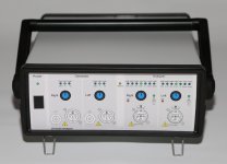
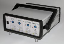
I have attached a couple of pictures showing approximately what it is expected to look like. The front panel is just a drawing at this point, but I hope it will give you an impression of what it will look like when finished.
The handle is optional.
The feet, including the two tilted ones, I expect to be standard.
The enclosure will be a bit deeper than the one shown in the pictures. It will be extended by 90mm compared to the one shown.
JensH
Just a quick status update.
The development of the electronics (5 boards) has been finalized. I just need to update a few components in the library. Next step is to hand it over to procurement and manufacturing to run a pilot series. Getting all the parts and setting up the assembly will take some weeks. The exact schedule is not known at the moment.
I have also worked on the mechanical design, selecting a suitable enclosure, making sure that the internal placement of boards, transformer, mains switch etc. is OK.
I have attached a couple of pictures showing approximately what it is expected to look like. The front panel is just a drawing at this point, but I hope it will give you an impression of what it will look like when finished.
The handle is optional.
The feet, including the two tilted ones, I expect to be standard.
The enclosure will be a bit deeper than the one shown in the pictures. It will be extended by 90mm compared to the one shown.
JensH
Attachments
Hi Jens,
That's ok. Looking forward to see the result of the pilot series. So far it look very good.
Mogens
That's ok. Looking forward to see the result of the pilot series. So far it look very good.
Mogens
Jens, what is the meaning of the warning symbols on the outputs?
Gesendet von meinem D5803 mit Tapatalk
Gesendet von meinem D5803 mit Tapatalk
The warning symbols may not be needed in the final version. The intention is that you should not put a DC voltage on the output. This may destroy some of the resistors in the output stage, which is DC-coupled.
I met with AKM today. They say the about to be released AK4497 should get to -120 dB THD+N, however the AP2722 even with tweaks from AP can't measure that low. They are awaiting an APX555 that may be able to measure its performance. All the harmonics are way down on both chips and its really limited by noise. Unfortunately the footprint is different (needed more pins for ground and references) so new PCB's. The plus (a really silly one) is support for 8X DSD.
For a simple point of reference using industrial models; The ShibaSoku 725D's distortion residue monitor output into a QA401 (AG16B source being used) looks like this:
 ...... 0 = -100dBv
The 725D can directly measure harmonics to -130dB; The Panasonic VP2277A can directly measure to -140dBv. Then from thier monitor outputs into QA401/FFT can get to -150dB, with high accuracy (<1/2db).. The AP2722 indicates exactly the same measured values at these ultra-low levels.
THx-RNMarsh
Last edited:
Hi 2 picoDumbs ,
They are standard BNC outputs. You can make your own, or buy them from all kinds of vendors.
-Chris
They are standard BNC outputs. You can make your own, or buy them from all kinds of vendors.
-Chris
I mean the amp output to xlr into analyzer as shown in the picture (assuming picture is accurate)
Hi 2 picoDumbs,
Same with the XLR connectors. You just have to be careful you don't exceed the maximum voltage in. You would normally be monitoring across some load resistors as well.
-Chris
Same with the XLR connectors. You just have to be careful you don't exceed the maximum voltage in. You would normally be monitoring across some load resistors as well.
-Chris
Hi 2 picoDumbs,
I don't expect test leads to be part of the delivery. There will be different needs depending on the test setup.
You can definitely cut a standard cable and mount e.g. banana/alligator clips if that is what you need.
If you have a single ended amp output you may still benefit from the differential input since it can eliminate the ground currents.
Take a look at this page for information about System Interconnects.
Sound System Interconnection
If you use something similar to fig. 13 you still need to make sure that you connect the ground of the analyzer to the ground of the amplifier. Otherwise the common mode signal (mains hum and DC offset) may get outside what the analyzer can handle.
You can also use something like this if you have a BNC cable.
NA2MBNC - Neutrik
But in that case there may still be some noise from the ground currents, depending on your setup.
JensH
Yes, a dedicated terminal can be useful in some situations. I will definitely consider adding that.
I'm assuming the xlr plug into the audio analyzer section is used for testing both balanced and single ended signals.
Does the instrument need to know what sort of signal is being tested from the output of the amp or does it automatically recognise what type of signal is being fed into the analyzer?
Does the instrument need to know what sort of signal is being tested from the output of the amp or does it automatically recognise what type of signal is being fed into the analyzer?
- Home
- Design & Build
- Equipment & Tools
- DIY Audio Analyzer with AK5397/AK5394A and AK4490