NicMac
But anyway I could not repeat that, nor with 0dBV signal nor with -10dBV signal.
Are you sure that your input range is 10V?
Here it is what I get:
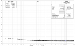
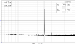
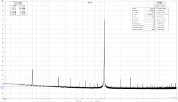
RTX input range 10V, first signal 0dBV(1V rms), than signal -10dBm(316mVrms):
https://www.diyaudio.com/forums/attachment.php?attachmentid=794719&stc=1&d=1573729197
https://www.diyaudio.com/forums/attachment.php?attachmentid=794719&stc=1&d=1573729197
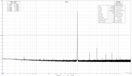
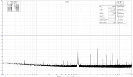
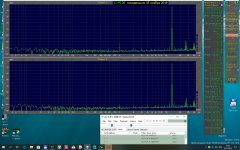
On 3,16V(10dBV) RTX input range the same signals looks like:
https://www.diyaudio.com/forums/attachment.php?attachmentid=794720&stc=1&d=1573729351
https://www.diyaudio.com/forums/attachment.php?attachmentid=794721&stc=1&d=1573729501
Obviously you input range was 3,16V(10dBV) and not 10V
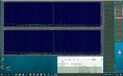
Your input signal is -9,99V not as stated 0dBv.Here is how mine looks.
0dB output range, 10dB input range, 0dBV REW generator.
But anyway I could not repeat that, nor with 0dBV signal nor with -10dBV signal.
Are you sure that your input range is 10V?
Here it is what I get:
RTX input range 10V, first signal 0dBV(1V rms), than signal -10dBm(316mVrms):
https://www.diyaudio.com/forums/attachment.php?attachmentid=794719&stc=1&d=1573729197
https://www.diyaudio.com/forums/attachment.php?attachmentid=794719&stc=1&d=1573729197
On 3,16V(10dBV) RTX input range the same signals looks like:
https://www.diyaudio.com/forums/attachment.php?attachmentid=794720&stc=1&d=1573729351
https://www.diyaudio.com/forums/attachment.php?attachmentid=794721&stc=1&d=1573729501
Obviously you input range was 3,16V(10dBV) and not 10V
Attachments
-
 -10dBV signal on 10V RTX input range.png131.3 KB · Views: 568
 -
 0dBV signal on 10V RTX input range.png132.6 KB · Views: 581
 -
 0dBV signal on 3,16V RTX input range.png138.9 KB · Views: 579
 -
 -10dBV signal on 3,16V RTX input range.png136.5 KB · Views: 556
 -
 -10dBV signal 339A on 3,16V RTX input range.png130.3 KB · Views: 111
Last edited:
I will try to reassume again what NicMac had shown:
He had set the front panel control switches :
Input section : to 0dB (1Vrms)
Output section: to 0dB (1Vrms)
Then he had set the dac output value to -40dBFs (or 10mV) . I do not know what is the correct name convention in Rew, it should be like 'generator settings'.
That is all that is needed.
Nicmac has done it properly right, also I had been asking for that.
Ciao, George
Reducing the level in the digital realm has the effect of reducing the ENOB. You aren't using as many bits to represent the signal, and that will increase the distortion.
I use an unmodified HP 339A as well along with the RTX. They each have their strengths and weaknesses. So which one I use depends on what I'm doing.
-Chris
I use an unmodified HP 339A as well along with the RTX. They each have their strengths and weaknesses. So which one I use depends on what I'm doing.
-Chris
Figure the RTX operates at an internal level of 3V. For 10V out there is gain. For 1V out there is an attenuator in the chain. Similar for the input side. However the SNR penalty is higher for the input side. This is true of all analyzers whether digitally based like the RTX or all analog like the HP. For example the AP performance numbers are all measured at around 3V to get the best results.
Now it is clear to me(and I also should use bigger FFT length),Figure the RTX operates at an internal level of 3V. For 10V out there is gain. For 1V out there is an attenuator in the chain. Similar for the input side. However the SNR penalty is higher for the input side. This is true of all analyzers whether digitally based like the RTX or all analog like the HP. For example the AP performance numbers are all measured at around 3V to get the best results.
Demian, George, NicMac, mbrennwa and Chris - many TNX

Last edited:

But.. Your (otherwise fantastic!) analyzer program says it's an EMU card?
Which one, 12/16/18? (M) I suppose that it's modified?
Very nice!
Mine (a 1616m) , after modifications, is producing similar results to the RTX..
Ciao, George
Which one, 12/16/18? (M) I suppose that it's modified?
Very nice!
Mine (a 1616m) , after modifications, is producing similar results to the RTX..
Ciao, George
You have done very well job here, my congratulation!
I see a THD difference btw two channel, at -9dBFS signal one gives 0.000109 the other 0.000045, due to the 2nd and 3rd harmonics. At -3dBFS the first one channel has more 2nd that the other channel.
Is that due from signal generator or difference in values of ADC electronic parts?
I see a THD difference btw two channel, at -9dBFS signal one gives 0.000109 the other 0.000045, due to the 2nd and 3rd harmonics. At -3dBFS the first one channel has more 2nd that the other channel.
Is that due from signal generator or difference in values of ADC electronic parts?

Looks interesting. Could you please describe the test setup and your results in more details?
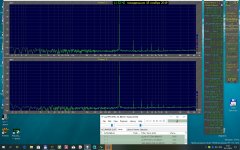
Foobar (ASIO)= CS4398 plays wav files received in ARTA Software. Analyzer=oscillometer Shmelyoff (ASIO)=ADC=AK5394A
Spectrum Analyzer FFT, Audio Generator. Анализатор спектра, Звуковой генератор
Spectrum Analyzer FFT, Audio Generator. Анализатор спектра, Звуковой генератор
Attachments


This is a front end for the EMU PCI series, right? Is it SW addressable or HW only?
Any idea about the costs please? Official website?
Any idea about the costs please? Official website?
Dear Vovi,
May I ask You why do you play a wav file?
Are there some problems in the driver scheme (software) ?
Arta is having a very nice generator setup..
Then, just would like to point out that these results are even better then they seem - - they are made on single ended outputs!
Ciao, George
May I ask You why do you play a wav file?
Are there some problems in the driver scheme (software) ?
Arta is having a very nice generator setup..
Then, just would like to point out that these results are even better then they seem - - they are made on single ended outputs!
Ciao, George
- Home
- Design & Build
- Equipment & Tools
- DIY Audio Analyzer with AK5397/AK5394A and AK4490