Michael,
That Prism App is a very cool program. Is it possible to add a second prism to simulate the true effects of a dual prism lens?
Materials -
Perspex, Lexan and evem Plexi-Glass are all types of Acylic. There is a fusing glue available that basically melts the pieces together and makes a water tight seal. Currently I am using 6mm Perspex but I am looking at Plexi-Glass as it is supposed to have the best transperency of the three. Even though the Perspex looks good, the plastics engineer that made both sets of prisms for me has stated that Plexi-Glass will give the best results, but it does cost more and I would have to purchase the entire 2400mm x 1200mm (8 x 4 foot) sheet.
Prism sizes -
The very best way to find the size you need is to conduct the paper test. Basically hold a piece of paper in the light path and draw the size of the rectange of projected light at (or as close to) the lens, and then some 4 inches away. Because I am using the SONY HS-3 (a very short throw 16:9), I had to build my prims large. My prisms are 220mm x 112mm. I built them rectangular, but most commercial lenses are square. Just make sure that the light path will not be clipped by either the prisms or the housing.
Each prism (in my 1st lens) are based on a right angle triangle of 30/60/90 degrees and have the hypotinuse facing the projector (prism 1) and facing the screen (prism 2).
My 4 prism lens is a little different in that each main prism has been split down the middle to create two chambers, so that there are now two 15 degree apexes inside the main 30 degree tip.
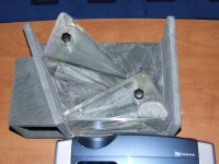
Yesterday, I drained them and took them back to the Plastics guy to have them glued to a mount plate. Only one is fixed directly to the plate (the plate is just a 10mm peice of Perspex that is 220mm x 250mm) and the second prism is joined to the first by an Acrylic hinge. This allows me to move the front prism (without accidentally moving the rear prism) to give me a pass through (no stretch) mode so that I can watch non anamorphic material without having to remove the lens.
I had been testing this with some double sided tape and some packing tape to form the hinge and it worked like a charm. I had a major re-alignment issue with the lens after the prisms were glued for some reason, but all is good now and the front prism can swing from an angle between the two prisms from 0 to 60 degrees, where about 40 degrees gives optimal stretch with no light reflections on screen...
Mark
That Prism App is a very cool program. Is it possible to add a second prism to simulate the true effects of a dual prism lens?
Materials -
Perspex, Lexan and evem Plexi-Glass are all types of Acylic. There is a fusing glue available that basically melts the pieces together and makes a water tight seal. Currently I am using 6mm Perspex but I am looking at Plexi-Glass as it is supposed to have the best transperency of the three. Even though the Perspex looks good, the plastics engineer that made both sets of prisms for me has stated that Plexi-Glass will give the best results, but it does cost more and I would have to purchase the entire 2400mm x 1200mm (8 x 4 foot) sheet.
Prism sizes -
The very best way to find the size you need is to conduct the paper test. Basically hold a piece of paper in the light path and draw the size of the rectange of projected light at (or as close to) the lens, and then some 4 inches away. Because I am using the SONY HS-3 (a very short throw 16:9), I had to build my prims large. My prisms are 220mm x 112mm. I built them rectangular, but most commercial lenses are square. Just make sure that the light path will not be clipped by either the prisms or the housing.
Each prism (in my 1st lens) are based on a right angle triangle of 30/60/90 degrees and have the hypotinuse facing the projector (prism 1) and facing the screen (prism 2).
My 4 prism lens is a little different in that each main prism has been split down the middle to create two chambers, so that there are now two 15 degree apexes inside the main 30 degree tip.
Yesterday, I drained them and took them back to the Plastics guy to have them glued to a mount plate. Only one is fixed directly to the plate (the plate is just a 10mm peice of Perspex that is 220mm x 250mm) and the second prism is joined to the first by an Acrylic hinge. This allows me to move the front prism (without accidentally moving the rear prism) to give me a pass through (no stretch) mode so that I can watch non anamorphic material without having to remove the lens.
I had been testing this with some double sided tape and some packing tape to form the hinge and it worked like a charm. I had a major re-alignment issue with the lens after the prisms were glued for some reason, but all is good now and the front prism can swing from an angle between the two prisms from 0 to 60 degrees, where about 40 degrees gives optimal stretch with no light reflections on screen...
Mark
Interesting problem
Mark,
Thanks for the further info. You seem to have arrived at a very workable solution. I would note though, that if you are thinking of trying different materials Lexan is a polycarbonate whereas Perspex and Plexi are acrylics. PCs and PAs have somewhat different refractive indexes. This could affect the direction of the reflections with your present design.
Unfortunately the little prism app is somewhat limited. It is very nice though for visualizing just how these internal reflections work and how they change with changes in refractive index of the materials involved. There are other apps on the same site that also seem like they could be useful for similar purposes. This pdf file also explains some info about how to calculate the amount of loss to reflection and ways to counteract the loss.
Light loss at interfaces
I think I will start looking into getting a couple of prototypes bent.
Thanks,
Michael
Hi Michael,
That's interesting, I did know that Lexan is Polycarb...
But it might come in handy if one prism was made from Lexan and the other made from Perspex for that exact reason - different reflecive indexes...though both of mine are the same material (Pespex) and filled with the same liquid (water) and I wouldn't say that it is bad. Sure there is room for improvement, but it seems to have given me the results that I wanted...
I hope you have as much luck as I did and look forward to reading more on your project...
Mark
That's interesting, I did know that Lexan is Polycarb...
But it might come in handy if one prism was made from Lexan and the other made from Perspex for that exact reason - different reflecive indexes...though both of mine are the same material (Pespex) and filled with the same liquid (water) and I wouldn't say that it is bad. Sure there is room for improvement, but it seems to have given me the results that I wanted...
I think I will start looking into getting a couple of prototypes bent.
I hope you have as much luck as I did and look forward to reading more on your project...
Mark
Curved screen
Mark,
You are using a curved screen, correct? Does that improve the focus with you current lens? How is the focus without a curved screen? Any other differences when projecting onto a flat screen vs curved? I'm kind of tied into a flat screen.
I've spent most of the day searching for info, reading and digesting optics. My head hurts.
Thanks,
Michael
I've been watching this thread on and off for some time now. Its been alot of fun watching you guys (re) design things from the start that have been around in the Cnema world for many many years now. Being a Cimena Technician and a collector of "Bent Glass"(anamorphics lenses both camera and projector) I really admire your intuition in the designs I've seen and the non-stop attempts by alot of people to build them. You have all gone alot further that I probably would have with it!!
Keep up the great work! You're all part of what makes this site such a great place......
Mark
Keep up the great work! You're all part of what makes this site such a great place......
Mark
That's interesting, I did know that Lexan is Polycarb...
That should read DID NOT know there was a difference...
It seems I can only edit my current post and reading that back makes me sound very arrogant...It's amazing how one word can change the meaning of the entire text...
You are using a curved screen, correct? Does that improve the focus with you current lens? How is the focus without a curved screen? Any other differences when projecting onto a flat screen vs curved? I'm kind of tied into a flat screen.
I am indeed using a curved screen. It is a PVC material about 3mm thick that laser cut letters are stuck to. It is flexible, but still rigid enough to stand. I have got it seated in 2 aluminium tracks that are fixed to the frame at the left and right only. The speaker baffle is three pieces hinged. As I bend the left and right panels in to aim the speakers to the sweet spot, the screen flexes also. Its not perfect, but it seems to work to correct barreling.
According to an earlier poster, HE lenses exhibit "pincushion" and VC exhibit "barrel" distortion.
For some reason I have a bit of both. My understanding for this is because the light beam of a typical HT projector works from one edge (top or bottom) where real cinema projector's light beams start at the centre of the lens and work out symmetrically. Therefore the barrel distortion I get is one side being the bottom for me as the projector is mounted inverted. The pincushion varies and right now is worse on the left than it is on the right. This could be made more symmetrical by rotating (twisting) the anamorphic lens. As a result, the image is slightly more in focus on one side.
I am not sure I have the right thing now. Originally I had two separte prisms, but then I came up with the "hinged" idea which worked when the "hinge" was just some packing tape. Now that I have the prisms glued, I can't seem to get the image looking as good as when the photo of Jango Fett was taken and there is no way I can get them apart with out issue...
I also saw some light reflections too last night that I had not seen prior. They are most def related to the amount of stretch. Too much, and they are there, and you reduce the amount to the point where they just disappear and then the goemetry is correct. The other issue for me is that my projector suffers a fair amount of overscan. Because a very small portion top and bottom of the image is missing (along with the black bars), the projected AR is slightly diferent to what it would be if the entire image was projected. The way I see it, my screen is 985mm x 3215, but by trying to stretch the image to fit the 2.35:1, I am effectively over stretching the image because I think I need to work off the image and adjust the screen (I can change the width with varible side masking bars) rather than trying to fit the image into the screen.
From what I can see, trying to stretch the image to fit the screen is like trying to change the AR with the lens. The screen might be 985, but the image (not including the part that is clipped) is actually less because of the over scan. Therefore I need to take that into account. It is difficult to explain here. Does any of that make sense?
I've been watching this thread on and off for some time now. Its been alot of fun watching you guys (re) design things from the start that have been around in the Cnema world for many many years now. Being a Cimena Technician and a collector of "Bent Glass"(anamorphics lenses both camera and projector) I really admire your intuition in the designs I've seen and the non-stop attempts by alot of people to build them. You have all gone alot further that I probably would have with it!!
Hello Mark,
Yes I agree, at times it might seem like we are trying to re-invent the wheel, but we are just trying to achieve a ccmmon goal, but do so without the huge expense of buying a commercial lenses. I love cinema, and to replicate that experience in my home means I have to step out of the square, right out side in some cases...
Mark
Onward
Mark T,
Thanks for the clarification and update on your system. I see you have met the Murphy analogue to the Heisenberg Principle, ie. permanent attachment of any two objects results in radically inferiour performance to that obtained in test system.
As I mentioned in my last post I am currently suffering from indigestion caused by optic formula overload.
Mark G,
Since you have a lot of these highly desired items underfoot perhaps you could post some measured drawings or orthoganol photographs with scale (metric). Scans of any literature included would be kind of cool too.
Thanks,
Michael
Hi Michael,
I just spent about an hour trying to re-align the lens (again) and I have to re-do the mount. I have no pass through mode again (well the front prism swings back but hits the inside of the case) so watching 1.78 looks all wrong as there is some stretch being applied, not the true pass through mode I had.
I don't understand how the prism could be offsetting the light that much. My 1.78:1 looked more like a diamond than a rectangle...Wthout the lens, the projector was level, yet stretching a 4 x 3 into 16:9, the image was all out of whack vertically...
The 2.35:1 setting looks OK now so long as there is not straight vertical lines on the far left (they look bent from the pincushion) and I can not get enough latteral movement to compensate. It was much easier to align them when they were separte...
But removing the lens tonight was nice and easy as you just grab the plate and whole thing comes out as one peice...
As for those "glass prism" lenses that Mark G mentioned (and you've asked about), they may be 2x stretch rather than the 33% we need.
I am working on a new plan that will be easier to construct. I will post details as they develop...
Mark

Distortion
Hi Mark,
Sorry to hear about the new problems with the permanently mounted prisms. Do you think that you could have had some small vertical offsets in the past that worked the cure on parallelagram shape? Is there any chance you could do some experiments with a laser pointer?
I'm not sure I understand your newest drawing, but if it represents 2 prisms composed of 2 elements each then I think you are on the right track. From my readings I take that each prism should be achromatic in itself. This result is obtained by composing it of two prisms with different materials with different refraction indices and using different apex angles for each. I have the formula for calculating the angles based on known refraction index and Abbe number so now I need to find these values for a variety of materials and do some number crunching. There are of course many other aspects that have to be considered. I am just trying to get a grasp on what those are.
As for Mark G's commercial lenses, if they are prismatic types the aspect ratio should be adjustable and, in fact, it is the adjusting mechanism that is of most interest to me right now.
Thanks,
Michael
As for Mark G's commercial lenses, if they are prismatic types the aspect ratio should be adjustable and, in fact, it is the adjusting mechanism that is of most interest to me right now.
All of the present day cinema anamorphics are all ground optics of super high qulaity, not prismatic. I do still have two customers up in Montana still using the old prism attachments though. There are many advantages and disadvantages in each of those type but the most interesting type and one that would work the best and give the lowest amount of Chromatic aberation is the Delrama Mirror type.
I have alot of lenses here but the most interesting ones are the Delramas, The D-150 Super Curvalon, and the Panavision Camera 65 lens.... the latter is a prism lens with a spherical prime lens mounted to the housing.... focal length is 57mm for a 65mm 5 perf camera frame or super wide angle. This lens is one of the actual lenses that photographed both "Raintree County" and "Ben Hur". I had a Delrama camera attachment... (extremely heavy and bulky!) but traded that away a year or so ago for another interesting lens.... it was not in a usable state. There are photos of that loens on the American Wide Screen Museum.
P.S. I will try to post some shots of both the Delramas and the Camera 65 lens later tonight.
Mark
I'm not sure I understand your newest drawing, but if it represents 2 prisms composed of 2 elements each then I think you are on the right track. From my readings I take that each prism should be achromatic in itself. This result is obtained by composing it of two prisms with different materials with different refraction indices and using different apex angles for each. I have the formula for calculating the angles based on known refraction index and Abbe number so now I need to find these values for a variety of materials and do some number crunching. There are of course many other aspects that have to be considered. I am just trying to get a grasp on what those are.
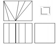
Basically put, the angles represent two prisms in a box. I've kept this design as a sinple 2 prism lens. Starting from the left is a 30 desgree prism, then an air gap then the second prism followd by the end on the lens. The angle are based on my current set up (that I know can work🙂) but rather than complex construction using the strip heater, I want to make a jig and glue everything in place. naturally there is some room for error and I will most likey have to give it a few goes as the angle between is what I fear the most - too much gives light reflections and not enough gives incorrect geometry. There should be a small (about 3 degrees) angle off the first prism, but I figure the whole assembly can be rotated here. The other idea is to create a lens that when used on way is a HE, or reveresed and turned 90 degrees can become a VC...
I'll be making a new for my exsisting lens before I go too far with this new project...l
I have alot of lenses here but the most interesting ones are the Delramas
I've seem some photos (I'm sure there are some in the pages of this very long thread) and they look really big and bulky. I guess what Michael and myself are really chasing is the angles to bend the light...
Mark
That particuluar Delrama of which there is a link to in an earlier post is the camera variety(made for Technicolor by Panavision back in the late 50's) and while there are two prisms the actual interference surfaces(if you will) are curved and silvered. Its that silvered coating that was damaged in my lens and I believe is visible in the photos of it on American Wide Screen.
HOWEVER.....The Delramas that were used as projection attachments are nothing but two curved opposing front surface mirrors... the curve caused the image distortion and with almost zero chromatic abberation! Chromatic abberations still plague the prism and cylindrical ground anamorphic types until you get into the 6 element attachments.
I forgot to mention that the Camera 65 lens is fixed at 1.25 squeeze... as is my projection attachment. The system was originally intended as a 1.33 squeeze but after initial testing it was determined by MGM that the 3 to 1 image ratio was way to wide and it was reduced to 1.25... which is still a very wide 2.75 to 1 aspect ratio unsqueezed . This same process after Ben-Hur and MGM obligations were fulfilled was re-named Ultra Panavision.
Mark
HOWEVER.....The Delramas that were used as projection attachments are nothing but two curved opposing front surface mirrors... the curve caused the image distortion and with almost zero chromatic abberation! Chromatic abberations still plague the prism and cylindrical ground anamorphic types until you get into the 6 element attachments.
I forgot to mention that the Camera 65 lens is fixed at 1.25 squeeze... as is my projection attachment. The system was originally intended as a 1.33 squeeze but after initial testing it was determined by MGM that the 3 to 1 image ratio was way to wide and it was reduced to 1.25... which is still a very wide 2.75 to 1 aspect ratio unsqueezed
. This same process after Ben-Hur and MGM obligations were fulfilled was re-named Ultra Panavision.Mark
HT vs T
Mark G,
I understand that chromatic aberration would present a major problem for movie theatre use of prismatic lens. In a movie projection system you are dealing with a white light source and therefore aberration between any two wavelengths would cause a visible anomalie. Thus the prisms have to be corrected for all visible wavelengths. For home theater the light is composed of only three to six wavelengths. Three in the case of LCD and 3 color DLP projectors. In the 80 page long patent that was referenced early in this thread the inventor demonstrated that correction at three specific wavelengths with a two component prism was not problematic. He also set forth the method of selecting the proper glasses from the characteristics that are commonly published in the glass catalogs. Not to go to deeply into the methods described, the problem for the diy'er is to find a less expensive and more easily workable material than optical glass. It is possible that a pair of plastics could be found or a plastic and a glass, or a glass and a glass that when combined with the proper liquids could produce a satisfactory result.
I have seen the mention of using two different liquids to form the prisms and I think that is on the correct path. I have not seen any mention though of using liquids whose refractive index matches the index of the glass or plastic that it is contained in. In my view this is a necessity. Otherwise light loss and reflections result at every interface. At best this gives a dimmer picture and loss of contrast, at worst visible reflections onto the screen and perhaps other distortions. Also for best quality I think each prism has to be achromatic on it's own. Due to the many angles of incidence of the light I don't think it is possible to have really good correction over the entire screen using the correction abilities of two separated prisms.
The next problem faced with the prismatic system is astigmatism. If the prisms could be place prior to the primary lens system where the light is collimated this would not be a problem I think. It might introduce other intractable problems of which I know not. Of course for use with a commercial projector as Mark T and I are using it would not be viable to modify the existing optics in this manner. In any case I guess that is the last bridge and if it is broken cannot be known until all other problems are dealt with.
The curved mirror solution is of course very elegant. It is, however, probably not possible for the diy'er to form complex 3-d curved first surface mirrors. Two component cylindrical lenses would most likely make a most suitable HT lens as well. Again it is not amenable to diy, but could perhaps be ordered from somewhere for not too much money. I guess if I could have components made for a hundred or so and only have to worry about the housing and adjustment scheme I would consider that.
Sorry for the ramble. Look forward to seeing the photos of your collection.
Thanks,
Michael
The next problem faced with the prismatic system is astigmatism. If the prisms could be place prior to the primary lens system where the light is collimated this would not be a problem I think. It might introduce other intractable problems of which I know not. Of course for use with a commercial projector as Mark T and I are using it would not be viable to modify the existing optics in this manner. In any case I guess that is the last bridge and if it is broken cannot be known until all other problems are dealt with.
I remember reading (in this thread) about some one who had pulled their DLP apart to do just as you have described. My concern was how he would adjust the prisms once the projector was re-assembled. There was never any follow up that I recall and I was hoping to read about it as being a positive result...
CA is something we are going to have to live with if we want to use a DIY lens. The amount I get is slight compared to the WOW factor that I get, and as I have stated before, for what this project has cost so far (in total less than AU$300.00 for two sets of prisms and varing cases), it is very well worth the effort and the $$$spent
Whilst it is not perfect, it is very workable (and user friendly), and I just want to be able to replicate it here for a bit less than the complex bent Perspex prisms I have right now...
Mark
Workable
Mark,
I think your screen shots show that you have arrived at a very workable solution. My suggestions are aimed only toward a theoretical "ideal" solution, not a negative comment on your results.
I too read the post from the person that pulled their projector apart. Since mine has just embarked on it's three year warranty, I don't think I will be doing that.
Besides the CA it is very important to me that the contrast ratio is not degraded as that is why I went with DLP over LCD. Well that and the sealed light engine.
Michael
I really do want to see a DLP through this lens. The levels didn't change as much as some announced, though I did increase the contrast from 72 to 78. Brightness (using a player that passes PLUGE) was set to 33, and rose to 34 for the 2.35:1 image, but remained at 33 for the 1.78:1. There was some colour shift, but all correctable to an acceptable level. Sharpness remained at zero. Even though the lens does soften the image (I can still see pixel structure) the sharpness did not need to be increased...
I am impressed with your quest to solve the reflective and reflractive index question. I've seem to have put it all in the too hard basket for now.
So have you come up with a lens design that you want to try?
Mark
I am impressed with your quest to solve the reflective and reflractive index question. I've seem to have put it all in the too hard basket for now.
So have you come up with a lens design that you want to try?
Mark
Did a complete re-alignment on the projector and lens tonight and once again I am happy with the image. I will still have to make a new case as the one I am using now does not quite allow the front prism to move far enough back to form a true pass through. The cause of the reflections is actully the base of the triangle and when brough far enough around will let light out the sides. Over the week end, a can of flat balck spray paint and some masking tape are in order...
Mark
Mark
Attachments
good news
Mark,
That's good news that you got the lens back working to your satisfaction.
I went to a plastic fabricator today and found out they want $100 to route some grooves in base and top pieces. They didn't sound too enthused about the bending thing. Also tried to track down some anti-reflective glass locally. Will hear more on that on Monday. Unfortunately it was then that the water pump decided to quit working on my van so it was from there to the shop and a too large bill. To make matters worse it won't be finished until Monday and I forgot my optics book and notes in it. Crap, looks like I don't make much more progress this weekend.
Michael
That's not good news Michael...
I have revisted that design I posted earlier. Rather than bending, which is both time consuming (therefore expensive) and not always guaranteed to be perfectly vertical (I found this with my second set of prisms, probalby why I have found it so hard to align) due to the amount of sanding needed to smooth out the "bumps" that occur at the bend.
So I am thinking about an all glue project. I will go back to my MDF supplier and get him to cut me the wedges I need (his saw is very accurate) to set the angles. If I use 25mm MDF, the vertical sides will be higher (25mm) and therefore should be easier to clamp for glueing.
So basically I need different wedges at 15, 30, 40, 50 60 and maybe 80 degrees and intend to work the lens as two opposing L shapes (1 prism per L) and then join the two after.
I also wan't to make the HE lens so it can be reversed at turned 90 degrees to form a VC lens as well.
I have attached the revised diagram showing the 2 L plan (insert). I won't be able to do any work on this project until middle to late next week, but will try to get a quote for the materials on Monday...
Mark
Attachments
- Home
- General Interest
- Everything Else
- The Moving Image
- Optics
- DIY anamorphic lens