Your 1 kHz tone bursts have severe overshoot you will have to try to trigger the signal better and expand the time base a bit.
The peak 1 kHz overshoot on the right channel in comparison to the left, are you using the silicone damping on this measurement ?
Yes. I used the damping device.
Tone bursts look excellent with quick returns. Not sure what is causing the slight double image
It may be an operational factor. I have to admit that I am not too good at using an oscilloscope. I need to get familiarized with the oscilloscope more.
It looks like multiple sweeps superimposed on each other. I suspect a trigger adjustment(s) on the scope would clear it up.
Ray K
Yes. It can very well be the reason.
Your triangulated looking 1 kHz square wave looks like it is bandwidth limited. If the RIAA response dropped off rapidly above 2 kHz, I would expect this shape waveform. Translating that into the mechanical domain assuming you are not going through an RIAA EQ stage), and reading the test record notes, it seems the cart<>arm system track-ability might be limited at high velocities
What confuses me is why the same 1 kHz square wave but on different test LP got a different result. Everything else is all the same. I have two phonos. One is Aesthetix Io. However, the Aesthetix is an all-tube phono and has too high noise level. I used Rotel phono to do all the tests only.
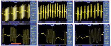
Here I tried these tests again. I expanded the time base for 1 kHz square waves. I also recorded burst tests at different frequency ranges. The original signal is from 500 Hz to 20 kHz.
I have never seen any company revel the same tests for their arms, so it is kind of difficult to compare my arm with other arms.
Attachments


Last edited:
Time for a slightly off topic story about the hazards of air bearings when you have to deal with management or pointy haired boss.
I once worked at a company that made machines that cut circuit boards out of a panel using a router that usually spinning around 30,000 rpm. The spindle usually lasted only a few thousand hours before it would require a rebuild. We looked at an air bearing spindle for our newer line of machine we were designing.
We were a smaller division of some larger company and at some point they decided we needed an actual president instead of borrowing someone from some other division. We were not so impressed with our new president and things really went downhill when we decided to have a look at an air bearing spindle.
We had a design review meeting discussing the pros and cons of an air bearing spindle. Supposedly it would not ever need bearing replacement as long as you did not crash the spindle into something hard.
One person noted that the spindle needed 90 PSI of air but the concern is it consumed it at a rate of 2.5 CFM. Many places may not have enough air capacity for that.
Dear president immediately pipes up and asks "How much is that in bars?"
A bunch of confused engineers listened carefully and someone explained that the 2.5 CFM was air volume. Dear president did not understand that statement and asked the question again. A few brave people tried to explain the difference between air pressure and air volume knowing it could be a career limiting move if they are not tactful enough with their answer. After many tries, we reached a point where we though we had explained enough and the president quit pressing for an explanation.
We eventually proceded with the air bearing spindle though without the president. A few unfortunate events like this and a few well respected departed employees forced a leadership change.
Member
Joined 2019
And suddenly the president replied:.. and someone explained that the 2.5 CFM was air volume.
- No, CFM is air volume RATE! 🙂
Hi Jim,
Your square wave plots look excellent. The divisions on the time axis don't seem to fit for a 1khz tone. What is the time per division? Just eyeballing the plot and looking at the period of the overshoot would suggest that you have a resonance at 17khz. This overshoot is well damped and decays almost instantly with no ringing. If this is the primary bending mode of the arm, which I suspect it might be, then this is very impressive and should result in a very neutral sounding arm. I think the square wave from the other test record is probably mislabelled and is actually just a triangular wave. The burst tones also look very clean.
Niffy
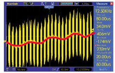
Looking the burst tests, I was puzzled by the extra information which is not suppose to be there. Please see the red waveform in the diagram. I tried to disconnect the input from the arm. I could still see the waveform there. It was a 60 Hz signal. I guess the wires may pick up the signal somewhere or the phono generated the signal by itself.
Attachments
The divisions on the time axis don't seem to fit for a 1khz tone. What is the time per division?
Niffy
I wanted to be sure and came home to check the manual. It is at 200 microseconds.
Attachments

Last edited:
Doh! I was looking at the minor grid marks and completely missed the major. It would still show the resonance at around 17khz so still very good.
Niffy
Niffy
Doh! I was looking at the minor grid marks and completely missed the major. It would still show the resonance at around 17khz so still very good.
Niffy
Hi Niffy,
When you said resonance at 17 kHz, I am not sure exactly what you meant. How did you look the screen shot to get such conclusion?
Jim
Hi Jim,
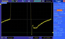
I was looking at the corners of the square wave. On each one there is a slight overshoot and about a single oscillation before it is lost below the noise floor. I've tried to zoom in on a single corner and highlight the part that I am talking about. Unfortunately I am trying to do this on my phone which combined with the resolution of the original is making things difficult to clearly see.

The highlighting didn't come out too well but hopefully you can see it. In this image a single wavelength appears to be slightly greater than a single minor division and is probably about 50us. This is better than I thought when I eyeballed it and would indicate a frequency of 20khz, which would be fantastic. Due to the limitations of the resolution it is difficult to be precise.
I assume that this recording was made using riaa equalisation. This will attenuate the higher frequencies and make them more difficult to clearly see. A more accurate picture of what the arm is doing would be obtained if the test was made without any equalisation. You could plug the output of the cartridge into a line level input of your amplifier and take the readings from the speaker outputs to give a bit of extra gain.
Niffy
I was looking at the corners of the square wave. On each one there is a slight overshoot and about a single oscillation before it is lost below the noise floor. I've tried to zoom in on a single corner and highlight the part that I am talking about. Unfortunately I am trying to do this on my phone which combined with the resolution of the original is making things difficult to clearly see.
The highlighting didn't come out too well but hopefully you can see it. In this image a single wavelength appears to be slightly greater than a single minor division and is probably about 50us. This is better than I thought when I eyeballed it and would indicate a frequency of 20khz, which would be fantastic. Due to the limitations of the resolution it is difficult to be precise.
I assume that this recording was made using riaa equalisation. This will attenuate the higher frequencies and make them more difficult to clearly see. A more accurate picture of what the arm is doing would be obtained if the test was made without any equalisation. You could plug the output of the cartridge into a line level input of your amplifier and take the readings from the speaker outputs to give a bit of extra gain.
Niffy
Yep. Looks like about 20k. And well damped with very little ringing. Absolutely brilliant.
Niffy
Niffy
“What confuses me is why the same 1 kHz square wave but on different test LP got a different result. Everything else is all the same. I have two phonos. One is Aesthetix Io. However, the Aesthetix is an all-tube phono and has too high noise level. I used Rotel phono to do all the tests only.”
If you are using different test LP’s you will get different looking scope shots - the output levels may not be different and I’d expect the cart/stylus to interact with this as well.
On the scope shot with the overshoot, it might possibly be tracking related.
Do you have a sweep track you can run to look for resonance?
Do you have a sweep track you can run to look for resonance?
I do have a sweep track. Do you mean arm/cartridge resonance?
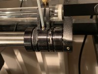
I found the headshell of my one of 1” air bearing dropped by itself. It destroyed the cantilever of a Sound Smith re-tipped Denon DL-103R, a $450.00 value. The reasons for the painful lesson happened were the imperfection of the contact area between the headshell and air bushing and incorrectly mixed epoxy. I made it manually so it didn’t fit the air bearing perfectly. The epoxy I used might not be mixed correctly since it was not hard enough.
So, I am back to the drawing board and going to have some else to make it for me. The damaged arm was about 135 g. I plan to make one around 100 g. A 1” air bushing is about 85 g already. The highest total mass I may make is 110 g.
It is also a caution for all DIYers. You need to make sure the epoxy you use is mixed correctly if you use epoxy.
Attachments

Ouch !
Looks like there might have been a slight film on the mounting headshell as well.
I always use MEK or acetone after scuffing the mating surfaces
A youtuber did some shear tests on many epoxys and found JB weld ( liquid steel ) held the best overall. 4 hour cure time.
This was the epoxy I used on the strain gage when I glued the boron MR into the stock cut cantilever
Really cant go wrong with stuff
Regards
David
“What confuses me is why the same 1 kHz square wave but on different test LP got a different result. Everything else is all the same. I have two phonos. One is Aesthetix Io. However, the Aesthetix is an all-tube phono and has too high noise level. I used Rotel phono to do all the tests only.”
Has it been mentioned that the STR112 does NOT have RIAA, a square wave out comes from a triangular groove for a perfect velocity transducer. Several of the STR series are technical in nature and not intended to just be used with a consumer RIAA pre-amp.
Apologies if this has already been mentioned.
EDIT - I looked back at the original post, yes the STR112 plot is what you get. You have to use a flat pre-amp to get a square wave.
Last edited:
Has it been mentioned that the STR112 does NOT have RIAA, a square wave out comes from a triangular groove for a perfect velocity transducer. Several of the STR series are technical in nature and not intended to just be used with a consumer RIAA pre-amp.
Apologies if this has already been mentioned.
EDIT - I looked back at the original post, yes the STR112 plot is what you get. You have to use a flat pre-amp to get a square wave.
Thanks for the info! That makes sense.
Thanks for the info! That makes sense.
You could also apply an inverse RIAA to what you do get out of an ordinary pre-amp.
Hi Jim,
Bummer about the failed glue joint and damaged cartridge. As mentioned, use a good quality brand of epoxy, the dime store stuff tends to be rubbish. Also cleaning and keying the surfaces will help. If you can keep the components firmly clamped until the glue has fully cured. I don't know what the maximum temperature that you can safely expose an air bearing to. If you can, whilst still clamped, place the assembly in an oven and bake at 80-100°C for an hour or two. After the elapsed time switch off the oven and leave the assembly in the oven to cool slowly. This can dramatically increase the strength and hardness of the epoxy.
Good luck with the rebuild.
Niffy
- Home
- Source & Line
- Analogue Source
- DIY Air Bearing Linear Arm