
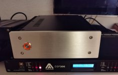
So, here is a rather boring form factor compared to the above... I managed to squeeze everything in a fairly small enclosure, everything is working fine and I even have a fancy led power switch.
Bias is at 0,45VB and 25.5 V, heatsink temperature is 45C at max.
Sounds better than the one with standard parts, I used an Audio Note tantalum resistor at the input, Takmans otherwise, good mkp caps, and Nichicon KW as outputs.
Sweet sounding now after quite a long burn in time, like it more than my EL84 SEP with approximately 4 Watt. And I like this one a lot...
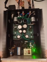
Attachments
Hi, I have a question. Will the chassis baseplate 230 mm wide from the diyAudio store work as a heatsink for the mosfets or do I need dedicated heatsinks? I plan to build it in the same chassis as my Whammy 🙂 . Thanks!
Yes, I'd like to know if there is chassis that can work w/o heat sinks as well. That would be pretty great.
This is squarely in the realm of “try it and find out”.
Will there be some amount of aluminum plate that will move enough heat away from the output devices to keep them in thermal equilibrium at a suitable temperature? Yes, absolutely. How big is that plate? No idea…
And of course, once that chassis is warmed up, the heat has to go somewhere, usually the air. Will anything be on top of that chassis? Will it have good airflow around the bits that are getting hot? Etc…
There is no simple answer of “yes, use the X chassis, will work for sure.” BUT, I am sure that there would be a solution that works exactly as you envision. You have to experiment.
One thing to remember, the heatsinks that the ACAmini was designed around have pretty good thermals, and they operate in free air, which is a best-case scenario for heat removal. https://www.digikey.com/en/products...ion-of-boyd-corporation/530002B02500G/1216384
As additional info maybe try this software (I have not tested it); https://www.heatsinkcalculator.com/flat-plate-heat-sink-calculator.html
IIRC you have a total of 10W/ch to dissipate in heat.
IIRC you have a total of 10W/ch to dissipate in heat.
This is not a whammy and it has different requirements. Check out the specs of the heatsinks from the ACA Mini Bom and then decide wisely.
Sorry for a newbie question: I would like to like/approve one of the posts above but do not find a way how to do so. Also did not find an answer in the help thread right away.
Is there a thread where I can find out how to do so, or are my options just limited because I am a new one?
Thank you!
Is there a thread where I can find out how to do so, or are my options just limited because I am a new one?
Thank you!
It could be a new user thing. You might want to ask here: https://www.diyaudio.com/community/forums/forum-problems-feedback.37/
I have a question about offset. I have two identical ACA Minis and they both have the same behavior with DC offset spiking when bias switch is turned on and off. They are biased to .33V and VB is 11.5. They both use 22K for R4 as per NP's comments. The offset goes as follows and is pretty much identical on both amps (I've timed how long it takes to settle down):
PSU gets plugged in (bias switch is off) : 180mv
Bias tuned on, climbs to 3.6v in 14 secs and then starts to slowly fall.
At 3 minutes 20 seconds, offset has fallen to 30mv (yay).
At 8 minutes 50 seconds it has settled to its resting place at 5.5mv (double yay).
When bias is shut off, offset spikes to 3.26v.
Is there any way to get rid of these spikes?
^ If that's with no load; try adding a load. Inputs shorted. Output loaded.
I guess, the more appropriate question is…what are you measuring?
DC voltage on the speaker outputs.
^ If that's with no load; try adding a load. Inputs shorted. Output loaded.
Ok thanks I'll measure that.
The output capacitor blocks DC but on power up, the voltage is increasing (AC) so for a short time, the changing voltage results in some current flow.
So would it be beneficial then to have a speaker protection circuit on the output? 3.6V over an 8 ohm impedance is 1.62 watts (for a short period of time as A Jedi states). This sounds similar to the 'fart' sound we hear with the original ACA, I figure the capacitor is charging up (especially with the RCA/SE input). This doesn't occur when the outputs are bridged/balanced.
@A Jedi - do you hear any crackle or pop sounds from your test loudspeaker?
I have a feeling that I have never measured such voltages on startup on my builds because I almost always use a Guardian 86 or 686 on my outputs. There is a 5 second delay before the speaker outputs are engaged/made active. As to whether the Guardian 86 circuit affects the sound, there is room for debate there, but not in my experience!
Best,
Anand.
If the 3.6V was without speaker attached into a 1k resistor (I think it's 1k ohm), then the current is about 4mA. 4mA into 8 ohms would be a very small voltage. Correct me if I'm wrong about this.
The primary difficulty is that ACA is almost always constructed in a small, tight fitting chassis with not much room for another PCB (speaker protection).
The secondary difficulty is that the ACA is a Class-A circuit, pulling relatively huge current out of a switch mode power supply. As you're aware, SMPS's have relatively little output capacitance. So when you switch the supply off, the DC voltage falls to zero in less than a millisecond. Much much faster than a relay can engage or disengage. So you need a speaker protection circuit that's a whole lot faster than a relay.
The secondary difficulty is that the ACA is a Class-A circuit, pulling relatively huge current out of a switch mode power supply. As you're aware, SMPS's have relatively little output capacitance. So when you switch the supply off, the DC voltage falls to zero in less than a millisecond. Much much faster than a relay can engage or disengage. So you need a speaker protection circuit that's a whole lot faster than a relay.
- Home
- Amplifiers
- Pass Labs
- DIY ACA mini