My amp camp mini is running a pair of horn speakers and it's a very nice combo. In my system it seems to sound right with the amp camp preamp and the jumper in the amp installed.
Where to go from here? What First Watt amps have a similar sonic signature? What's the upgrade path?
Where to go from here? What First Watt amps have a similar sonic signature? What's the upgrade path?
Maybe start here;
https://www.diyaudio.com/community/threads/sound-of-various-pass-amps.253334/
Check post no.6 by NP.
https://www.diyaudio.com/community/threads/sound-of-various-pass-amps.253334/
Check post no.6 by NP.
Having a problem with my new ACA Mini...
I was the lucky winner of an ACA mini at the last Burning Amp Camp and finally was able to assemble it. This is my fourth Pass DIY project and although I'm pretty much a "paint-by-number" guy, I've been successful and very happy -- but I'm having trouble with this one. The power supply puts out 24v, but when I plug it in, it begins pulsing. I've noted the early post about problems with the power supply and have turned the amp on and off while waiting -- but it continues to pulse. I was not able to adjust the bias and I did smell something hot -- turns out that is in the upper right area. C6 and R8 are much hotter than anything else on the board. I'm pretty sure everything was assembled correctly, and I did go over everything to check for improper soldering. I've included some photos -- pardon the fuzz I now see from cleaning the back of the PCB and I do see dark residue in some places from the Fire-Metall?
Any help any of you might provide would really be appreciated. Thanks very much, David
Attachments

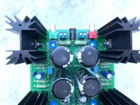
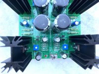
That is it!Verify the Q3 positions have 9520 mosfets and the Q4 positions have 520.
Even with your beautiful guide -- I mixed up the right side.
Thank you 6L6!

nice ,clean better the flux 😉That is it!
Even with your beautiful guide -- I mixed up the right side.
Thank you 6L6!
sorry ...but i am searching for this comment..
but my browser quit all sites
We note that this 2nd harmonic character is the mostly result of the differences between Q3
and Q4, where the P channel Mosfet on top has lower gain than the N channel. That's fine if
you like your negative-phase second, but maybe not so much if, like many audiophiles, you
prefer lower distortion.
However, this is adjustable by varying the degeneration on the output devices. Slightly
lowering the resistance on Q3 will raise the gain, improving the balanced between Q3 and Q4
and lowering the amount of 2nd harmonic. You could do this by simply using a lower value
resistor, but we find that this results in greater bias drift with temperature.
However, you can parallel R8 with an RC network consisting of a power resistor in series with
a capacitor to get the same effect for AC, leaving the DC character alone. Typical values for
the resistor would be from zero to several ohms. In the case of this circuit, it works out that
something from about .75 ohms to 1.5 ohms does the trick.
which thread was that?
thanks in advance
chris
Chris,
The passage you quoted came from the ACA mini article. See page 9 here: https://firstwatt.com/pdf/art_aca_mini.pdf
The passage you quoted came from the ACA mini article. See page 9 here: https://firstwatt.com/pdf/art_aca_mini.pdf

may i ask once again..
sorry....i was off with audio...more then a year.
i remember a article or a post by EUVL (XENaudio) about the trick with the degeneration resistor (R0,47 and a new 0,1R parallel) and trimmer and cap for AC....
cant find it.
sorry....i was off with audio...more then a year.
i remember a article or a post by EUVL (XENaudio) about the trick with the degeneration resistor (R0,47 and a new 0,1R parallel) and trimmer and cap for AC....
cant find it.
Good evening,
I have a question regarding possible substitutes for the TO-220 heatsinks. My enclosure is not tall enough to fit the board mounted 2.5" heatsinks.
Could the 4 pc Mosfets Q3,Q4 be bolted on my aluminium enclosure frame to maintain 20W dissipation specification @60 deg. C ? If so, what would be the total area required per Mosfet for proper heat dissipation? Each of my panel are 8" X 2.5" X 3/8"
Thank you so much
Enclosure I plan to use (less old junk inside):
https://drive.google.com/file/d/1OlHSc8tDhdfqjwt3ysY-0iPSslAr1HWq/view?usp=sharing
Can you do it? Yes.
Will it work? Don’t know. Perhaps. You’ll have to try. I suspect it will work, but will be pretty warm.
Remember that the point of the heat sink of to get the heat out of the device, and then to the air around it. So maximize the enclosure’s ability to heat the surrounding air.
Also remember that the mosfet bodies will have to be electrically insulated from the chassis.
Can you do it? Yes.
Will it work? Don’t know. Perhaps. You’ll have to try. I suspect it will work, but will be pretty warm.
Remember that the point of the heat sink of to get the heat out of the device, and then to the air around it. So maximize the enclosure’s ability to heat the surrounding air.
Also remember that the mosfet bodies will have to be electrically insulated from the chassis.
Or another option is ordering the 2” vs 2.5” board mounted heatsink, heat dissipation performance may not be the same. What about doing a hybrid Mosfet mount + heatsink bolted on frame..
Last edited:
- Home
- Amplifiers
- Pass Labs
- DIY ACA mini