That will not work as well, as the heat sinks will be inside the still air of the box, getting hot, and that has a much worse path to the outside.
What about just building it as designed? It was never really meant to go in an enclosure.Or another option is ordering the 2” vs 2.5” board mounted heatsink, heat dissipation performance may not be the same. What about doing a hybrid Mosfet mount + heatsink bolted on frame..
There's a lot of margin here, as the heatsink temperature is only a bit lower than the transistor junction temperature, and it can operate at fairly high values.

Why not? This is my next build, waiting for the FQP transistors. Bottom and Topplate perforated to enable air circulation. Compared to my first builts just 1/2 high unitWhat about just building it as designed? It was never really meant to go in an enclosure.
kids…pets…why dress a beautiful girl ? 🙂
Because there’s a difference between building an enclosure around the amp and trying to force the amp into an existing enclosure.Why not? This is my next build, waiting for the FQP transistors. Bottom and Topplate perforated to enable air circulation. Compared to my first builts just 1/2 high unit
View attachment 1114833
.....which is why I laid out new boards to work properly with a little conventional chassis. It was the pricier way to go and kinda defeats the whole Mini zeitgeist ... but I really like it. It fits most rooms better than a bare board. The next build will use an ACA chassis! The blank chassis was just 20% off for Black Friday at Modushop. I've got improved boards now, too and... some Fairchilds from @KevinHeem to pop in to the next build.Because there’s a difference between building an enclosure around the amp and trying to force the amp into an existing enclosure.
What about just building it as designed? It was never really meant to go in an enclosure.
Because there’s a difference between building an enclosure around the amp and trying to force the amp into an existing enclosure.
I think I'm going to walk these two statements back...it is DIY after all. 😉
This is such an excellent group and the ACA Mini exemplifies engineering-type minds that optimize for maximum efficiency, while allowing for architect minds to apply self-imposed design parameters that either look cool (in their eyes) or add a feature such as implied safety. You guys are awesome.I think I'm going to walk these two statements back...it is DIY after all. 😉
Can you do it? Yes.
Will it work? Don’t know. Perhaps. You’ll have to try. I suspect it will work, but will be pretty warm.
Remember that the point of the heat sink of to get the heat out of the device, and then to the air around it. So maximize the enclosure’s ability to heat the surrounding air.
Also remember that the mosfet bodies will have to be electrically insulated from the chassis.
Good evening,
I have a question regarding possible substitutes for the TO-220 heatsinks. My enclosure is not tall enough to fit the board mounted 2.5" heatsinks.
Could the 4 pc Mosfets Q3,Q4 be bolted on my aluminium enclosure frame to maintain 20W dissipation specification @60 deg. C ? If so, what would be the total area required per Mosfet for proper heat dissipation? Each of my panel are 8" X 2.5" X 3/8"
Thank you so much
Enclosure I plan to use (less old junk inside):
https://drive.google.com/file/d/1OlHSc8tDhdfqjwt3ysY-0iPSslAr1HWq/view?usp=sharing
Getting there. Mounting heatsinks to the inside with thermal paste, still have to figure out the top plate design. Compact chassis, hardest and most expensive part now figured out!
Drill holes under and above the heatsinks for airflow. They are useless without airflow.
Stating the obvious:
Heat sinks are on the exterior of a chassis for a very simple reason: to maximize heat transfer from the metal to the surrounding air by allowing the heated air to escape (rise), replaced with cooler air from the surroundings. Although 6L6's advice is always, always spot on, I'm afraid you will be impeding heat transfer if your only drill holes. I believe you'll need air flow into the fins from the sides as well as from the bottom for adequate convection.
Of course, this is DIY, so try it and let us know how it turns out. - David
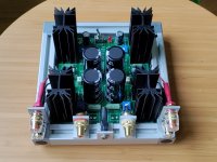
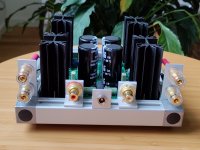
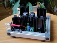
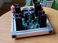
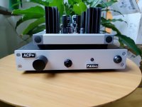
And open frame it is!
This is my first PPP (Papa's Push-Pull) and it really punches above its weight. 🥊
This is my first PPP (Papa's Push-Pull) and it really punches above its weight. 🥊
Attachments
-
 2022-12-02 10.33.16.jpg462 KB · Views: 248
 -
 2022-12-02 10.32.12.jpg405.7 KB · Views: 231
 -
 2022-12-02 10.32.05.jpg426.1 KB · Views: 228
 -
 2022-12-02 10.31.54.jpg406.2 KB · Views: 227
 -
 2022-12-02 10.31.35.jpg407.5 KB · Views: 223
 -
 2022-12-01 08.33.54.jpg326.3 KB · Views: 244
 -
 2022-12-02 13.43.35.jpg255.7 KB · Views: 242
Fuuuugly!!And open frame it is!
This is my first PPP (Papa's Push-Pull) and it really punches above its weight. 🥊
Looks cool but dust collector. Not for kids or pets aroundAnd open frame it is!
This is my first PPP (Papa's Push-Pull) and it really punches above its weight. 🥊
😀Fuuuugly!!
Thanks! And I should say that thanks to the frame weight there is no risk that it is pulled away by large cables. Better than I hoped.
That’s what I was thinking..or have a cut-out on the cover top plate above each heatsinks.Drill holes under and above the heatsinks for airflow. They are useless without airflow.
My Aleph J gets warm with huge heatsinks. Difference with this one the entire frame is thick aluminum so hoping will dissipate heat. Key is airflow I agree
- Home
- Amplifiers
- Pass Labs
- DIY ACA mini