Agreed, but the problem, as described, is not a reset but a return to 'Factory default' condition, normally only seen when both the up and down buttons are pressed simultaneously when applying power. The only other time 'FAC' normally appears is when a new SG4 chip is installed.
No new SG4 chip is needed (as far as I am aware). The unit has seen low to moderate use since it was completed six years ago and this problem has only arisen over the past month or so. Both times, I simply flipped the power switch on and the display presented the "FAC" message. So what's likely causing the problem?
The up and down switches, like the others, operate when pulled to ground, at other times they float.
What you could try is to add a 'pull up' resistor of a suitable value, say 22k, between the active side of each switch and the 5V supply.
What you could try is to add a 'pull up' resistor of a suitable value, say 22k, between the active side of each switch and the 5V supply.
Last edited:
Ralph:
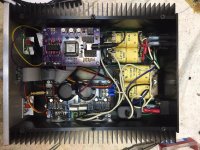
Thanks for the suggestion! I have a few spare, small momentary switches on hand. I could remove the Up and Down switches and replace them with ones that hang off a short piece of wire and a 22k resistor but, before I do so, it seems reasonable to also ask if my use of an encoder (hidden beneath the ribbon cable) could be contributing to the "FAC" problem.
Regards,
Scott
Attachments
I'd check the solder connections on each button with a multimeter- do a continuity check to see that the contacts are open. If they registered as closed even when you don't press the button, the chip will read closed no matter what other controls you have connected.
Certainly an encoder could contribute to the problem, they do seem to vary in quality.
Disconnecting it will at least allow you to eliminate it if the problem remains.
Disconnecting it will at least allow you to eliminate it if the problem remains.
I would like to purchase a pre-loaded SG4 chip. Is there anyone from the EU who could sell it to me? Thank you Marek
Hi All
I'm building the SG4 with a Rev-C board which has the I2C header over beside U2.
I want to use a rotary encoder (Bourns PEC11R-4220F-S0012) and I wanted to know if I'm okay to take Vcc and GND for it from the I2C header?
Thanks in advance for your help
Regards
Ian Carson
I'm building the SG4 with a Rev-C board which has the I2C header over beside U2.
I want to use a rotary encoder (Bourns PEC11R-4220F-S0012) and I wanted to know if I'm okay to take Vcc and GND for it from the I2C header?
Thanks in advance for your help
Regards
Ian Carson

Sorry I haven't answered earlier, but yes you can use the VCC and GND from the header; I would suggest that you add a small capacitor, maybe 0.22uF across the VCC and GND at the encoder end.
Before I go off an order pcbs, does anyone in the US have an SG4 board that they want to sell?
lehmanhill:
I have an extra couple of boards. PM me your name and address and I'll send one to you.
Regards,
Scott
I have an extra couple of boards. PM me your name and address and I'll send one to you.
Regards,
Scott
I have been looking at adding an LCD and from the initial post it looks like the necessary LCD has to be :1602 i2c PCF8574A
I have not seen how to specify the PCF8574A chip - most options list options for 0x27(PCF8574) , 0x38(PCF8574A) , 0x3F(PCF8574AT) and reference the address to be set by the chip. Clearly people have been able to buy the correct screen but it is not obvious to me how to make sure you get the correct screen and not risk random chance.
tia..dB
If you have the SG4 chip v1.05 then you can use either the pcf8574 or pcf8574A; SG4 v1.04 only works with the pcf8574A.
If you have an earlier version you will need a new SG4 v1.05 chip. Contact me via PM for details.
If you have an earlier version you will need a new SG4 v1.05 chip. Contact me via PM for details.
I got the first revision of the SG4 - suspect it was v1.04 , I will have to see if I have any data from Seth - no specifics just date to December 2021.
I am having no joy with the LCD screen. I have tried 3 different screens and all I get is the top row of squares. I have checked continuity of the leads and rechecked the solder joints several times.
Also checked voltage and it is 5.08v
This doesn't seem like it should be difficult but something is clearly not working.
Open to try anything should anyone have ideas. Thx.. dB
Also checked voltage and it is 5.08v
This doesn't seem like it should be difficult but something is clearly not working.
Open to try anything should anyone have ideas. Thx.. dB
- Home
- Source & Line
- Analogue Source
- DIY 4 Phase Sinewave Generator for Turntable Motor Drive