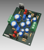
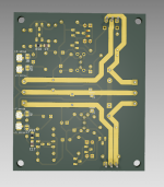
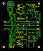
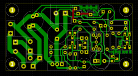
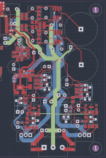
This is the dual MOSFET version of the negative feedback circuit. I made it so you can experiment with higher current output so there's only DC input. You should have a separate board/arrangement for rectification/filtering.
I tried to keep the high current tracks as short as possible. You should fill them with solder. Watch out for shorts.
This one can also be diyed. Board size is about 63mm x 75mm.
For part values you should follow the LTSpice sims posted or ask for your desired Vout, don't follow the Kicad schematic values.
These designs have not been tested yet so you make them at your own risk.
edit: I release these designs for personal use, no commercial applications.
Attachments
Last edited:


Why do you use such high capacitor values? You don't need them that high.
The only benefit of having an output capacitor is to keep the regulator happy so it doesn't oscillate. A 100uF cap would do.
The output impedance of the regulator is lower than that of the capacitor. You have no benefit from having an output capacitor higher than 100uF. I used a 470uF in my testing as that's what I had on hand. I see you added 8200uF on the output.
Just testing various values. Ignore them for now. I don't know what I will use in the end. However on the PCB I have let space there to use big values if needed. That is because I have seen differences in practice in sound, but you can ignore it for now.
I am also thinking a version of more power. I need 9A 60V. That means many FETs, everything else the same right?
I am also thinking a version of more power. I need 9A 60V. That means many FETs, everything else the same right?
I didn't try paralleling MOSFETs with this circuit yet. You could try it.
I don't know how high output capacitance would make a difference in sound. Maybe on other circuits it helped because of the particularities of those circuits?
I don't know how high output capacitance would make a difference in sound. Maybe on other circuits it helped because of the particularities of those circuits?
Both paralleling and adding sinus generator with rectifiers gives me more ripple.
Can we add a bridge and 50Hz source to see what happens? It gives me bad results.
Can we add a bridge and 50Hz source to see what happens? It gives me bad results.
If you are looking at the transient analysis of the circuit you should add more details for the components used. For example try adding the transformer secondary resistance to the 50Hz source.
But it's best to build the circuit and measure it instead of simulating.
But it's best to build the circuit and measure it instead of simulating.
yes, i will build, have ordered all parts from mouser and jlpcb, i hope i have time to build, i am particularly busy these days.
I don't know how to measure noise, so I ll trust my ears when everything is built.
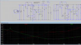
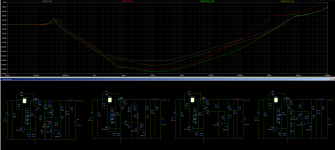
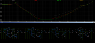
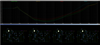
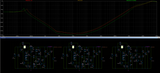
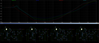
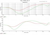
I attach a photo, where I try to simulate the variations of voltage from rectifier, because for some reason if i put the normal rectifier it won't work. Anyway even so, red curve with low CLC values and green curve with big CLC values (for the positive but it doesn't matter)
I don't know how to measure noise, so I ll trust my ears when everything is built.
I attach a photo, where I try to simulate the variations of voltage from rectifier, because for some reason if i put the normal rectifier it won't work. Anyway even so, red curve with low CLC values and green curve with big CLC values (for the positive but it doesn't matter)
Attachments
You can measure noise with an LNA and your sound card. (With software like REW.) The LNA can be as simple as a low noise op-amp (like 0.9 nV/√Hz AD797 or OPA1611/12) or can be more complicated with parallel PNP added to an NE5534 with TL071 offset servo. (Such as a 60 dB gain variant of Douglas Self's MC pre-amp.)
It does need to be constructed carefully with low noise supplies and some shielding. Steel cookie tins can help with shielding.
If you go that route just make sure you get the AD797 or OPA1611/12 from an authorized distributor so you don't get LM741 marked as AD797.
It does need to be constructed carefully with low noise supplies and some shielding. Steel cookie tins can help with shielding.
If you go that route just make sure you get the AD797 or OPA1611/12 from an authorized distributor so you don't get LM741 marked as AD797.
Last edited:
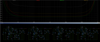
Instead of the current setting resistor in the denoiser circuit one could use a LED CCS.
I tried in simulation and I got good results. It does improve PSRR a bit on dienoiser configuration, but I think it's worth it more to add it to the simple denoiser circuit. The PSRR performance for denoiser with CCS is between simple denoiser and simple dienoiser, while the noisefloor should remain the same.
It also improves the output impedance of the regulator.
I tried to add this to the LM317 + de/dienoiser but the PSRR gains are small, and with denoiser the regulator noise dominates.
This is only tested in simulation at this point. I'll try to make this mod to my boards and measure the results.
I attached the simulation results.
edit: you basically get higher PSRR with the noisefloor of the denoiser, and closer to dienoiser output impedance. the CCS LED resistor should need a clean ground point. for higher output voltages you'd drop some heat into the CCS transistor, so consider this before designing any boards. maybe switch to a TO126 variant with a heatsink.
Attachments

Last edited:
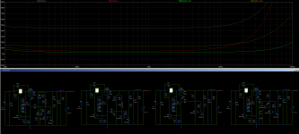
The negative versions of the circuits seem to get a boost in PSRR if the denoiser transistor is replaced with a 2N5401. For dienoiser it doesn't seem to matter what the upper transistor is, but if the lower one is 2N5401 then the PSRR gets a good boost getting them in line with their positive counterparts.
Might be due to the early effect? One issue is that I don't know what is the noise of 2N5401 in this configuration. I'll need to measure this to confirm it, but simulation seems to indicate an increase in PSRR for the negative versions.
Might be due to the early effect? One issue is that I don't know what is the noise of 2N5401 in this configuration. I'll need to measure this to confirm it, but simulation seems to indicate an increase in PSRR for the negative versions.
With the CCS you could also increase the denoiser current. If you can spare around 30mA on the output you can push the PSRR closer to normal dienoiser performance.
In the attached photo you can see CCS denoiser with about 8mA, CCS denoiser with about 30mA and normal denoiser and dienoiser (5-7mA).
edit: added a photo comparison for dienoiser with CCS at 30mA, dienoiser with CCS at 8mA and normal dienoiser at 7mA.
In the attached photo you can see CCS denoiser with about 8mA, CCS denoiser with about 30mA and normal denoiser and dienoiser (5-7mA).
edit: added a photo comparison for dienoiser with CCS at 30mA, dienoiser with CCS at 8mA and normal dienoiser at 7mA.
Attachments
Last edited:
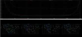
I added the CCS to the MOSFET board and took some measurements.
12.2Vout, 150Rload, 220uF filter capacitance so input ripple is at around 0dBV.
I tried a higher current of 22mA for the CCS but didn't notice any improvement vs 7mA. I used MPSAx6 pair for the dienoiser circuit, might try with other BJTs.
The denoiser version had a ZTX851 BJT.
PSRR results:
1. normal denoiser - 129.7dB
2. ccs denoiser - 140.1dB
3. normal dienoiser - 149.7dB
4. ccs denoiser - 151+dB. My measurement setup limit is around -150dBV. I tried without Rload and ripple was still at -150dBV. Since the other PSRR measurements are close to simulation ones then I suppose this value would be around 158dB.
Noise results:
1. normal denoiser - 0.64nV/sqrtHz (I think this might be with MPSA06)
2. ccs denoiser - 0.51nV/sqrtHz (with ZTX851).
3. normal dienoiser - 0.75nV/sqrtHz
4. ccs dienoiser - 0.71nV/sqrtHz.
I measured this noisefloor between 10kHz and 20kHz as my ADC has some LF noise.
Attachments
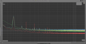
Got a new audio card with a better ADC so I wanted to make a better measurement of the supply. This time I used batteries to power the LNA and the DUT (for noise measurements).
I also made a new design for the negative feedback version, that also includes the CCS upgrade to the circuit. The board can still be diyed with only two topside wires. For fab house you don't need to install them. The board is also a bit smaller. Main filter cap is 18mm but you can install smaller ones.
The output current is limited by the rectifying diodes but if you short two of them you could use a separate rectification/filter board.
Measurement was done with 18Vin and 12.3Vout with 150R load for around 100mA total output. I used a 220uF input capacitor for an input ripple of around 0dBV. Compensation network is made out of 47nF + 1R. Output capacitor is a Panasonic FR 470uF/25V (20mm long version).
For noise measurements I used battery power for both LNA and DUT, for PSRR measurements I used batteries only for LNA. There's still some 50Hz pickup as I didn't put the board in a case, I had it on my desk.
I've done measurements for the following setups:
- denoiser with ZTX851
- dienoiser with MPSA56/ZTX851
- dienoiser with MPSA56/MPSA06
I don't have a ZTX951 but will get one with the next order.
In my configuration I drove the denoiser circuit pretty hard at around 22mA.
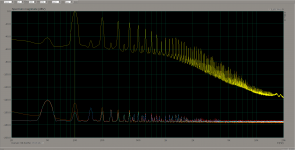
Results for PSRR:
denoiser with ZTX851 - 145dB
dienoiser with MPSA56/ZTX851 - 160dB
dienoiser with MPSA56/MPSA06 - 157.5dB
Results for noise (extracted the ADC+LNA noise, about 430pV/√Hz, from measurement):
denoiser with ZTX851 - 476pV/√Hz
dienoiser with MPSA56/ZTX851 - 573pV/√Hz
dienoiser with MPSA56/MPSA06 - 675pV/√Hz
Denoiser with ZTX851 seems to have a bit higher LF noise between 20Hz - 100Hz. The new ADC also seems to add some LF noise but not as bad as my previous one.
I included each measurement in the attached archives. I also attached a LTSpice sim file for the exact values I used in the measurement (apart from the input cap). I also added a configuration for the negative version. I used two red LEDs for Vref in the measurement, but I also included an example in the sim for a PM829 setup. The Zener diodes could be installed instead of the LEDs, vertically on the PCB.
edit: there's jumpers to switch between denoiser and dienoiser and also to bypass the CCS circuit if you want to use a regular resistor instead.
I also made a new design for the negative feedback version, that also includes the CCS upgrade to the circuit. The board can still be diyed with only two topside wires. For fab house you don't need to install them. The board is also a bit smaller. Main filter cap is 18mm but you can install smaller ones.
The output current is limited by the rectifying diodes but if you short two of them you could use a separate rectification/filter board.
Measurement was done with 18Vin and 12.3Vout with 150R load for around 100mA total output. I used a 220uF input capacitor for an input ripple of around 0dBV. Compensation network is made out of 47nF + 1R. Output capacitor is a Panasonic FR 470uF/25V (20mm long version).
For noise measurements I used battery power for both LNA and DUT, for PSRR measurements I used batteries only for LNA. There's still some 50Hz pickup as I didn't put the board in a case, I had it on my desk.
I've done measurements for the following setups:
- denoiser with ZTX851
- dienoiser with MPSA56/ZTX851
- dienoiser with MPSA56/MPSA06
I don't have a ZTX951 but will get one with the next order.
In my configuration I drove the denoiser circuit pretty hard at around 22mA.
Results for PSRR:
denoiser with ZTX851 - 145dB
dienoiser with MPSA56/ZTX851 - 160dB
dienoiser with MPSA56/MPSA06 - 157.5dB
Results for noise (extracted the ADC+LNA noise, about 430pV/√Hz, from measurement):
denoiser with ZTX851 - 476pV/√Hz
dienoiser with MPSA56/ZTX851 - 573pV/√Hz
dienoiser with MPSA56/MPSA06 - 675pV/√Hz
Denoiser with ZTX851 seems to have a bit higher LF noise between 20Hz - 100Hz. The new ADC also seems to add some LF noise but not as bad as my previous one.
I included each measurement in the attached archives. I also attached a LTSpice sim file for the exact values I used in the measurement (apart from the input cap). I also added a configuration for the negative version. I used two red LEDs for Vref in the measurement, but I also included an example in the sim for a PM829 setup. The Zener diodes could be installed instead of the LEDs, vertically on the PCB.
edit: there's jumpers to switch between denoiser and dienoiser and also to bypass the CCS circuit if you want to use a regular resistor instead.
Attachments
-
 Screenshot from 2021-06-09 07-50-03.png94.5 KB · Views: 278
 -
 Screenshot from 2021-06-09 07-42-12.png328.7 KB · Views: 306
 -
 Screenshot from 2021-06-09 07-41-40.png388.5 KB · Views: 343
 -
 Screenshot from 2021-06-09 08-38-50.png403 KB · Views: 352
 -
 noise.png301.2 KB · Views: 268
 -
 psrr.png91.6 KB · Views: 566
 -
discrete_dienoiser_ccs.zip293.4 KB · Views: 179
-
noise.zip771.5 KB · Views: 126
-
psrr.zip489.4 KB · Views: 131
-
Draft55.asc22.4 KB · Views: 173
Last edited:
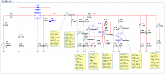
PSU denoiser with OpAmp.
OpAmp is OPA2197 .
.
OpAmp is OPA2197 .
.
Attachments

Last edited:
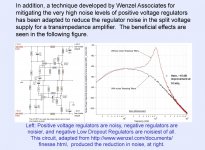
I wouldn't name that a denoiser: it is more a variation on Wenzel's "finesse" theme:
In addition, it is not discrete either: it relies on a monolithic regulator and an opamp, but I'll let Trileru judge the relevance of this addition to his thread
In addition, it is not discrete either: it relies on a monolithic regulator and an opamp, but I'll let Trileru judge the relevance of this addition to his thread
PSU denoiser with OpAmp (improved circuit).
OpAmp is LM833 .
.
Also, see WEB link below (english).
.
Finesse Voltage Regulator Noise!
.
OpAmp is LM833 .
.
Also, see WEB link below (english).
.
Finesse Voltage Regulator Noise!
.
Attachments
Last edited:
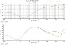
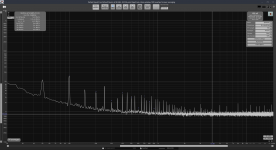
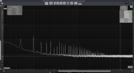
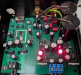
I made a new DAC pcb, and I used the mosfet discrete versions for the power supplies for opamps V+/V-.
I attached the analog part of the DAC pcb and noise density measurements for both rails.
I think the performance is completely overkill for this application.
When I'll upgrade this DAC I'll most likely use LM3x7 + simple denoiser. Simpler to implement, lower BOM and less space on the pcb.
First measurement is V+ and second one is V-.
edit: the measurements were made right under the opamps on the power traces.
Attachments

Last edited:
- Home
- Amplifiers
- Power Supplies
- Discrete regulators with denoiser