I have designed this DAC mostly just for my own fun, implementing only features that I need at home. I even didn't put any indications and LEDs,Agreed, and it can result in lower close-in phase noise if using good crystal clocks.
That said, its not clear what this dac can sell for. The high-sales-volume consumer market is mostly for dacs selling for no more than a few hundred dollars. Even the original Topping D90 was a bit too expensive at around $700.
Moving along into the lower end of the high end commercial market, there are dacs boxes still using dac chips, but with better circuitry surrounding the dac chip, and more bells and whistles.
At around $4.5k or so there are some lower end Holo dacs that are very popular with audiophiles. There are also some R2R type dacs and alow end Chord at closer $1k, but they don't sound very good.
The dac of this thread is of unknown SQ. It may not play DSD from an external source, it doesn't have much or anything in the way bells and whistles, etc. Unless it sounds as good or better than a Holo Spring 3 or similar (which can play external DSD, and has some bells and whistles) this can probably can't sell for more than, oh, maybe $2,400. Divide that by 6 gives 400. That means the complete dac, the manual, the shipping box, case, the power supply, the USB board, TOSLINK cable, factory testing, and whatever else, needs to have an incremental production cost of no more than $400. That's because nobody is going to buy a diy board for $2400 unless it sounds better than a Bruno Putzeys dac.
OTOH, how much could the DAC fetch as a diy product? Well, most people buying dac boards around here are looking for low cost. They may try a cheap discrete resistor dac, but very few will pay for an expensive diy dac board. Also, if you sell diy, you are going to have customers that need technical help and support. A one man operation has to provide that. OTOH, if you are in the high end commercial market, most warranty support, advertising, dealer recruitment, etc., type things will handled by regional distributors. The distributors get maybe a 10% cut of the selling price as their payment for the work they are responsible for. Dealers might get 30% of the selling price. The other 60% goes to the manufacturer. However, if you have distributors and dealers all over the world, you may end up better off by essentially paying other people to do part of the work.
because I hate them. It is literally simplest "plug&play" device ever for listening music. There is no firmware to update inside, no features to bother about.
The only thing absolutely required - the clock accuracy of you digital source must be inside +-100ppm.
And this DAC doesn't support DSD, I'm using
software like Foobar2k to convert it tp 192k PCM, SW obviously can do it better than HW, by using floats and doubles. DSD also has no value for
digital signal processing without being converted to PCM.
So far I'm actually very busy senior developer working very far from any audio, if the concept of this DAC is not interesting, I simply don't care.
It is funny, that using inexpensive FPGA and a handful of discrete parts it is possible to compete with best solutions on the market. Looks like audio is long abandoned area of E-engineering. Of course I don't mean B.Putzeys. He is just incredible.
There are some curves of other modulators at: https://pcmdsd.com/Software/PCM-DSD_Converter_en.html
Chrome translate can be used to read the text on some of the pages.
Regarding DSD, some people complain that the low midrange doesn't sound real. Its not full and warm like natural sound in a room. My guess would be there is too much signal-correlated noise in the frequency band where the ear is most sensitive. The correlated noise can mask the sound of natural, warm room ambience, would be my guess. IOW its not the noise floor that is the remaining problem.
Last edited:
The modulation of the noise floor is just another wording for correlated noise. It can be assessed by observation how much FFT noise floor changes width change of amplitude of 1khz tone. I found, that modulators with more aggressive NTF sound better, despite of a challenge to the reconstruction filter.The correlated noise can mask the sound of natural, warm room ambience, would be my guess. IOW its not the noise floor that is the remaining problem.
Understood that noise floor modulation is correlated noise. But there is correlated noise is the skirts that is more closely correlated with the signal. It isn't distributed across most or all bins.
The overall noise floor shows only the long tails of the problematic skirt correlated noise. Again, same basic problem as in radar.
The overall noise floor shows only the long tails of the problematic skirt correlated noise. Again, same basic problem as in radar.
The modulation of the noise floor is essential characteristic for 1-bit output, because power of signap+noise=const.
So if signal is changing the noise has to be correlated. I know the only remedy - really huge loop gain. Otherwise come along with multi-bits, having horrible issues with differential nonlinearities, DEM, DWA handicaps.
So if signal is changing the noise has to be correlated. I know the only remedy - really huge loop gain. Otherwise come along with multi-bits, having horrible issues with differential nonlinearities, DEM, DWA handicaps.
You left out a couple causal factors: Clock close-in phase noise, and Vref noise. For a discrete resistor RTZ FIRDAC, you can see how MarcelvdG designed his power supply for the final output logic devices. In his design, that power supply is Vref. Links to schematics at: https://www.diyaudio.com/community/threads/return-to-zero-shift-register-firdac.379406/


Maybe take a look at the references at the end of this:
https://www.analog.com/media/en/ana...le-ultra-low-phase-noise-dds-applications.pdf
My comment: you seem to be focused on the DSP aspect of FIRDAC design. The problems you may be overlooking are analog engineering design problems. A dac converts digital analog, right? The analog part of the dac needs to be good too. The clock is an analog time reference. Vref is an analog voltage regulator. IOW the analog part of the dac design is not only about output stage filtering.
Last edited:
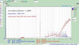
Thank you for the data; very interesting🙂. Does this mean that for a 0dBFS input, the output level becomes 0.54 (-5.35dBFS)?This is the performance of the entire digital path of the DAC. I mean 48K input up-sampled and filtered to 768x.
The output was taken from Verilog simulator. Additional moving average of 16 consequent data samples applied(FIRDAC model).
Input level was 0dB, that means about 0.54 modulation depth. FFT length - 2**20.
In the case of DSM (Delta-Sigma Modulation), whether it's 1 bit or multi-bit, the behavior is not the same for the positive and negative sides. Therefore, even in the digital domain, the elimination of even-order noise does not occur. In PWM (Pulse Width Modulation), the positive and negative sides operate symmetrically, and theoretically, there is no even-order noise, correct?I don't understand the source of the 2-nd harmonics on you attached pictures, because of digital output of the modulator
is always free from even harmonics. Simply by principal of operation.
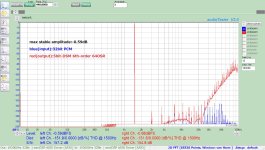
For modulators designed for multi-bit types like the AK4499EX, even-order components still remain, as shown in the attached file. However, when it goes below -140dBFS, the accuracy on the FFT side may become a factor. Additionally, as a fundamental issue with DSM, especially with 1-bit, there is some inconsistency, so the repeatability of THD at such levels is low. In practical terms, if it's below -140dBFS in the digital domain, it should not have any impact on the analog signal.
Attachments
IIRC, Rob Watts who designed the Chord series of DACs said that for his best design, the Chord DAVE, he found that as he continued to decrease THD in the digital domain, he and others could hear the sound continue to improve in the analog domain until the digital THD was at or below -280dBFS. So it set it to -300dBFS. He said he ended up needing a 17th order modulator. Also said he didn't know why he needed THD that low in the digital domain before it became inaudible in the analog domain (with his pulsed array conversion).
What he still got wrong was he used SMPS to power DAVE and the other Chord dacs. He was convinced it made no audible difference. However, many of his customers disagreed and modified their Chord dacs to use linear power supplies.
What he still got wrong was he used SMPS to power DAVE and the other Chord dacs. He was convinced it made no audible difference. However, many of his customers disagreed and modified their Chord dacs to use linear power supplies.
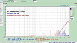
Yes, you are correct. More modulation leads to abrupt increase in distortions due to longer non-minimal phase delay in the feedback loop.Thank you for the data; very interesting🙂. Does this mean that for a 0dBFS input, the output level becomes 0.54 (-5.35dBFS)?
I always thought that correctly designed digital DSM is absolutely simmetrical. Negative numbers are not much different from positive, until saturation. Of course, 0x7ffff /= -0x80000.In the case of DSM (Delta-Sigma Modulation), whether it's 1 bit or multi-bit, the behavior is not the same for the positive and negative sides. Therefore, even in the digital domain, the elimination of even-order noise does not occur. In PWM (Pulse Width Modulation), the positive and negative sides operate symmetrically, and theoretically, there is no even-order noise, correct?
Additionally, as a fundamental issue with DSM, especially with 1-bit, there is some inconsistency, so the repeatability of THD at such levels is low. In practical terms, if it's below -140dBFS in the digital domain, it should not have any impact on the analog signal.
You are absolutely correct. Yesterday it was -142dB, today -140dB and no idea what will be tomorrow.
I don’t have so stable and precision tools at home to measure better. Another issue is that the harmonics from different origin cancel each other. This effect may change with time and temperature.
Markw4,
I think Rob Watts was kidding. Nothing comes for free.
First, even 8-th order NTF requires very long accumulators.
Sometimes Matlab or other standard tools can’t even calculate the frequency response correctly using doubles, custom algorithms, tolerant to truncation errors needed.
Another big issue is how to filter out 17th order quantization noise brick-wall.
And the last - long FIRDACs, pulse arrays and etc, have fundamental limitation in SNR and ENOB.
Digital noise is proportional to the number of taps, while strength of the filter - to sqrt(N).
I guess, SNR of 120dB is very close to absolute limit for discrete DAC of reasonable complexity.
For example, differential LPF of 6-th order with 800nVrms noise will use minimum 6 dual OPAMPs per channel.
Are you ready to design layout and shielding to provide such level of performance?
Dirty trick is to provide no less than ~5Vrms output just for getting SNR numbers. Than you have attenuate it to standard level and use an amplifier with typical 100dB dynamic range.
Last edited:
First of all, are we talking about close-in noise or noise floor? Also what does the noise sound like, hiss, popping, what? The more disagreeable it is, the more it calls for remediation.Are you ready to design layout and shielding to provide such level of performance?
Look, already there is work going on in other parts of the world as well as here where I am in the US to keep developing dacs. Also, patents continue to be filed to further advance dac technology. Its not as mature of an area of audio as are linear amplifiers.
What we find when we start shielding dacs sections from each other to cut down on radiated EMI/RFI coupling, when we reduce clock close-in phase noise, when improve analog power supplies, etc., is that the sound keeps improving. Yes, there are some diminishing returns. Its usually the case when an effort is made to get the highest performance that it becomes less and less cost effective. However, some of us are interested in exploring how good audio reproduction can be. For us, it costs what it costs.
In the case of what you have done with your adaptive clock, IIRC Soekris did something similar with a diy dac board he sold and or still sells. There were a lot of complaints about the sound due to that adaptive clocking scheme. Most of us who want good sound are using asynchronous USB and dealing with the isolation and shielding issues that come with it. At least we can use good clocks in that case. Other people beside me have already tried to give you some advice, which don't seem interested in. IMHO if aren't willing to listen to potential customers, you won't be very successful in business. The idea of, here I made this thing the way I want it, how many do you want to buy? That type of attitude usually tends to end up in failure. Even if you make it sound really good, its still hard to get enough people to give it a try. Maybe consider this: Most small businesses fail, but most people who start small businesses think they are smart enough to succeed when most other people will fail. Of course the failure statistic applies exactly to people who think they are smarter than everyone else.

I also use SMPS, it is much better than linear supply. No stray magnetic fields and harmonics in audio band.IIRC, Rob Watts who designed the Chord series of DACs said that for his best design, the Chord DAVE, he found that as he continued to decrease THD in the digital domain, he and others could hear the sound continue to improve in the analog domain until the digital THD was at or below -280dBFS. So it set it to -300dBFS. He said he ended up needing a 17th order modulator. Also said he didn't know why he needed THD that low in the digital domain before it became inaudible in the analog domain (with his pulsed array conversion).
What he still got wrong was he used SMPS to power DAVE and the other Chord dacs. He was convinced it made no audible difference. However, many of his customers disagreed and modified their Chord dacs to use linear power supplies.
And it is dirty cheap. Bulky linear PSU = marketing insanity. I had been working as SMPS designer for couple of years and about 16years, designing low noise analog in North America.
Except that they often produce conducted and or radiated EMI/RFI at a few MHz. It can bring its own set of problems. The conducted noise may be significantly common mode, but it can get mode converted into differential. Its not uncommon. The noise can get demodulated in forward biased semiconductor junctions and then intermodulate with the audio signal. This is a well understood problem. Some opamps are rather sensitive, and newer ones are designed with better tolerance. Either way, the idea that only noise in the audio band can cause problems is well known to be false.I also use SMPS, it is much better than linear supply.
So, what I would do is build a prototype that is clean and good as I can make it. Then I will see if I can use SMPS and keep the sound the same or maybe even make it better. IOW, there is some experimental lab work to do.
Here's a pic of Bob Pease working (if you know who he is):
Here's Jim Williams' lab:
IOW, sometimes its good to roll up your sleeves and do some R&D instead of sit in a chair and think of reasons why you shouldn't have to get dirty hands.
Last edited:
Markw4,
Thanks for advice, I’m listening to you. I have very limited time to work on the DAC and for chatting.
I just trying to explain what was considered more important and what - less.
Reference noise and jitter are of course important.
I just tried not to spoil the performance of SI552, which was considered adequate for audio.
It is better to use a couple of simple VCXOs instead, but I don’t have required frequencies.
I also bought and disassembled and studied famous Crystek oscillators - it happened to be pure marketing fame,
they have regular single CMOS 1G logic gate inside and primitive circuitry. You can easily design the same.
They don’t have even dedicated build-in low noise LDO.
About reference - it just needs proper filtering. AFAIK, Cosmos ADC uses filtered TL431 as reference.
None of us complained about its ability to measure distortions at the level of AP.
And of course I’ve done comparisons of the noise floor with SMPS and linear supply.
SMPS - was absolute winner.
Last edited:
Yes, I met Bob Pease personally and talked to him, when he visited Canada.
But I’m a designer of later generation and for me B.Putzeys and Lars Risbo are more interesting to listen to.
But I’m a designer of later generation and for me B.Putzeys and Lars Risbo are more interesting to listen to.
Yes, but there is more than distortion and noise to good sound. One of the big problems we have is that we don't know how to measure everything we know is physically important for music reproduction. There is stereo imaging for example, which is dependent on a number of cues that the brain uses to for spatial localization. There is also the correlated noise skirts problem. There is excess noise in resistors, there is a threshold of audibility for group delay. Dielectric absorption can cause linear distortion. Teflon insulation is triboelectric, most ceramic caps are piezoelectric, etc. However, we don't have published thresholds for everything that can cause audible artifacts.FAIK, Cosmos ADC uses filtered TL431 as reference.
None of us complained about its ability to measure distortions at the level of AP.
As possible food for thought, attached is a paper describing some of the things that humans listen for. I think its not too hard to see that measuring noise, distortion, crosstalk, etc., is not enough to strongly predict how an audio device will sound to the average ear, and or to other ears.
IME, clock close-in phase noise, resistor excess noise, piezoelectric capacitors, etc., tend to mask a fair amount of recorded information that most people never get to hear.
Attachments
Last edited:
Regarding clocks like Crystek, IME to work well they need to be well cared for by the dac designer. Crystek are not SOA clocks by any means, but they can sound decent if properly powered, bypassed, loaded, buffered, laid out where ground currents will not disturb the analog oscillator, etc. Attention to such things adds cost and complexity. However, reasonably decent performance is possible given some design effort beyond some of the typical simple example circuits shown in some datasheets. Example circuits may in part be intended to make it look low cost and easy to use the product in a design. The marketing department may have a lot to say about what does or doesn't appear in the datasheet.
For Crystek 957 in particular, IME they sound better with Rubycon MU series, 805 size, .22uf film caps for bypass (thanks to diyiggy for that advice). Same for the clock buffers. Don't drive distributed loads with the clock directly. Buffer it and load it with its recommended capacitance. Bypass the buffers the same as the clocks. Run both clocks continuously and switch their outputs with a small signal relay having gold contracts. Locate clocks in an area of the board where there are minimal ground currents, maybe in a remote corner or something like that. Power the clocks and maybe the buffers from a dedicated regulator. Try not to use ferrite beads as a matter of rote. They are not necessarily ideal. There is more that could be said, but will leave off here for now.
For Crystek 957 in particular, IME they sound better with Rubycon MU series, 805 size, .22uf film caps for bypass (thanks to diyiggy for that advice). Same for the clock buffers. Don't drive distributed loads with the clock directly. Buffer it and load it with its recommended capacitance. Bypass the buffers the same as the clocks. Run both clocks continuously and switch their outputs with a small signal relay having gold contracts. Locate clocks in an area of the board where there are minimal ground currents, maybe in a remote corner or something like that. Power the clocks and maybe the buffers from a dedicated regulator. Try not to use ferrite beads as a matter of rote. They are not necessarily ideal. There is more that could be said, but will leave off here for now.
Last edited:
Jim was a master of subtle analog craftiness - especially noise measurements. I once wrote him a letter congratulating him on a WSJ article recognizing his achievements and he called me on the phone. We chatted for nearly an hour. He was truly an engineering hero of mine. RIP, Jim.Except that they often produce conducted and or radiated EMI/RFI at a few MHz. It can bring its own set of problems. The conducted noise may be significantly common mode, but it can get mode converted into differential. Its not uncommon. The noise can get demodulated in forward biased semiconductor junctions and then intermodulate with the audio signal. This is a well understood problem. Some opamps are rather sensitive, and newer ones are designed with better tolerance. Either way, the idea that only noise in the audio band can cause problems is well known to be false.
So, what I would do is build a prototype that is clean and good as I can make it. Then I will see if I can use SMPS and keep the sound the same or maybe even make it better. IOW, there is some experimental lab work to do.
Here's a pic of Bob Pease working (if you know who he is):
View attachment 1261383
Here's Jim Williams' lab:
View attachment 1261384
IOW, sometimes its good to roll up your sleeves and do some R&D instead of sit in a chair and think of reasons why you shouldn't have to get dirty hands.
Sorry, please discard my previous answer. The right one is: at 0dBfs duty circle of PWM is (1+0.54)/2=0.77, physically it is 1.05Vrms.Thank you for the data; very interesting🙂. Does this mean that for a 0dBFS input, the output level becomes 0.54 (-5.35dBFS)?
Last edited:
- Home
- Source & Line
- Digital Line Level
- Discrete FPGA DAC project