Sorry Troy,
Your output buffer is backword. 🙁
You can probaby desolder it, just remove enough caps in front of it to get something small and flat under the chip. Something like a small screwdriver. just heat on leg at a time and gently pry that leg up while you have the heat on it. Slowly do all 8 legs and eventually the chip will come off. Be careful not to force it or you will pull the pads off the pcb.
There is a "1" on the PCb where pin #1 goes.
Sorry for your misfortune.
BTW I knew the kookaburra's nickname. The name is sort of an inside joke. An excercize in irony. 🙂
Uh... I don't tink toe as my son said as a child..
Just send me a new kit and a paypal invoice.
I will give this one to Repute(the guy who assembled my Rev_C) to fix and keep. He has a VERY nice solder(de-solder) staion with a good magnifying light.
Apparently I missed the 1 on the board. Oh well, that's what happens when you rush... All to sit and wait 2 weeks for my amp to return..
I cant seem to find any technical data, input and output impedances and headphone drivecapability?
frequency response?
frequency response?
Specs:
Input impedance is 100K when you use the input buffer.
Output impedance is that of the output buffer (which is to say very low, next to nothing).
Ouput current is about 45-60ma per channel depending on the opamp used for the output buffer. For the AD8620 it is in the 50ma range 🙂
I drive my Senn HD600s with this amp so it is very capable of driving even a stiff load like that. 🙂
I have not had a chance to actually measure the device for frequncy response or THD, but there is nothing in the circuit to limit the performance of either opamp nor the PG2311. I wish I had the facilities to more thouroughly test the electical characteristics, but I do not .... yet. 🙂
You could get a very good idea of the performance of the circuit by looking at the datasheet for the AD8620/OPA2227 and the PGA2311. Everything is well bypassed (analog and digital) and I use no external compensation which would limit the bandwidth.
Also note there are no input caps, if your source has DC you will need to add them prior to the circuit. This is very intentional as you almost never need an input cap, and the amp sounds so much better without it. I think one of the reasons this amp has such good dynamics in the simplicity of the design in regard to the signal path.
Cheers!
Russ
Nordic said:Is this a suitable preamp for a turntable?
Got one today
I have never tried it in that capacity, it is not designed as a phono stage, there is no RIAA filter. It would probably work, but the gain may be too low. You could actually pretty easily increase the gain by cutting one trace and adding two resistors on each side of the opamp at the output buffer. This would require a basic understanding of opamps, but it would not be hard.
I take it this mod would in turn make it too sensitive for my other equipment again...
No biggie, i'm sure there must be a good DIY phono pre out there...
No biggie, i'm sure there must be a good DIY phono pre out there...
Nordic said:I take it this mod would in turn make it too sensitive for my other equipment again...
No biggie, i'm sure there must be a good DIY phono pre out there...
Yep.
Nordic said:I take it this mod would in turn make it too sensitive for my other equipment again...
No biggie, i'm sure there must be a good DIY phono pre out there...
Go here for instance.
Take
jumper or-jg
hello and g'day,
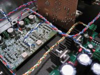
As mentioned before my pre will not work at all without this one jumper in. Anyways I was trying a few lower value resistors in that spot and also bypassing the resistor with some low value caps-100nf mfp and other ones.I got mixed results with nothing really doing anything except this last one: Every system is unique; what I ended up with was a 0r jumper by-passed with a axial 200vdc .1mfd. "silverfilm";I like it.
cheers
doggy🙂 🙂
hello and g'day,
As mentioned before my pre will not work at all without this one jumper in. Anyways I was trying a few lower value resistors in that spot and also bypassing the resistor with some low value caps-100nf mfp and other ones.I got mixed results with nothing really doing anything except this last one: Every system is unique; what I ended up with was a 0r jumper by-passed with a axial 200vdc .1mfd. "silverfilm";I like it.
cheers
doggy🙂 🙂
Do you mean from the 0r jumper to ground? A straight cap in the 0r jumper spot will not work at all for me;I tried a few different values. Brian I am happy, it's sounding good.
Just to inform; the pre was working all along with th 0r jumper in but I just wanted to see if I could match it better to my system.
doggy🙂 🙂
p.s doing my xmas polishing; he..he..
Just to inform; the pre was working all along with th 0r jumper in but I just wanted to see if I could match it better to my system.
doggy🙂 🙂
p.s doing my xmas polishing; he..he..
Attachments
Glad it's working and sounding good.
I just mean a 0-ohm jumper across the pins of a cap is shorting the cap, unlike a resistor that would send some current through the cap. I test would be to measuer voltage across the cap pins. Just curious.
I just mean a 0-ohm jumper across the pins of a cap is shorting the cap, unlike a resistor that would send some current through the cap. I test would be to measuer voltage across the cap pins. Just curious.
Current takes the path of least resistance, and there is NO voltage accross a short.
A cap accross a 0 (zero) Ohm jumper is non-existant.
Jumper to ground or V may have an affect, but accross (in parralell with) the jumper has none.
Sorry just Ohms law not mine.
A cap accross a 0 (zero) Ohm jumper is non-existant.
Jumper to ground or V may have an affect, but accross (in parralell with) the jumper has none.
Sorry just Ohms law not mine.
It must be fooling myself again. There is definitely something flowing between those two points. It could be the"proud papa syndrome"-
cheers
doggy
cheers
doggy
doggy said:It must be fooling myself again. There is definitely something flowing between those two points. It could be the"proud papa syndrome"-
cheers
doggy
Keep in mind that your 0 (zero) Ohm jumper may not be EXACTLY 0 Ohms..
But I would expect it to have to be off pretty far for a cap to be audible in that position.
Yes of course there is something flowing between those two points. 🙂 There is meant to be.
A bypass cap will not do anything for you but a very small resistance (like the jumper provided) or a 1-4.7R resistsor just provides a bit of isolation.
A bypass cap will not do anything for you but a very small resistance (like the jumper provided) or a 1-4.7R resistsor just provides a bit of isolation.
doggy said:It must be fooling myself again. There is definitely something flowing between those two points. It could be the"proud papa syndrome"-
cheers
doggy
While the analog part of the circuit has dual rails the digital portions only have V+ and GND(0V) so a cap in place of the jumper effectively blocks all current to the digital circuity, thus causing it not to work at all. 🙂 That is why it will only work when you have a small value resistor or a jumper there. The cap you added will always be swamped, and thus is doing you no good as the current will always take the easy path accross the jumper or resistor.
Good work! Very nice preamp. I hope you enjoy it. 😀
Cheers!

Russ
- Status
- Not open for further replies.
- Home
- Amplifiers
- Headphone Systems
- Digitally controlled preamp/headphone amp