BrianDonegan said:We are actually thinking of chaging the op-amp included in the kits to the OPA2227, and including both. This would help keep the cost reasonable,as the 8620s are pretty pricey. Anyone have an opinion about that?
Seems OK, if you put 'em in a socket you can always change 'em later, easily, if you think it could sound better.
Take
They are SOIC packages, so no sockets.
Or, you can redesign the PCB a little bit so that it can take a DIL socket and use one of thos ridiculously expensive Winslow adapters. 😉
Wnislow SOIC to DIL adapter
Completely off-topic but a wanted to ask this question for a long time now. Who's nose stood model for the Twisted Pair logo, your's or Russ's? 😀
I once met a man with a nose sooooo big he could smoke in the shower...
I hope it where cigarettes and not cigars, jeeez 😀
Well I don't know what kind of sound a Kookabura makes but my wife was laughing at me for giggling like a school girl when I saw my beta kit came in.
As usual it was packed for the gentle care of the USPS... 😀
I hope to build and stuff into my Rev_C amp this weekend.
Will post pics and details as they happen.
As usual it was packed for the gentle care of the USPS... 😀
I hope to build and stuff into my Rev_C amp this weekend.
Will post pics and details as they happen.
An externally hosted image should be here but it was not working when we last tested it.
Gee GeWa, I really like how your tube amp looks.
rabstg said:Well I don't know what kind of sound a Kookabura makes but my wife was laughing at me for giggling like a school girl when I saw my beta kit came in.
As usual it was packed for the gentle care of the USPS... 😀
I hope to build and stuff into my Rev_C amp this weekend.
Will post pics and details as they happen.
Awesome Troy, I am stoked to see how it turns out.

I kookaburra is actually a pretty funky sounding bird BTW. 😉 Not exactly like a school girl, but wild none the less.
Cheers!
Russ
Russ White said:
Awesome Troy, I am stoked to see how it turns out.
I kookaburra is actually a pretty funky sounding bird BTW. 😉 Not exactly like a school girl, but wild none the less.
Cheers!
Russ
http://www.nationalparks.nsw.gov.au/images/dacelo_novaguineae.mp3
For those who aren't able to hear them in their own country 😀
--Nathan
I for one wouldn't have any problems with replacing the ad8620 by any other opamp. It saves a lot of money on the kit and whenyou DO want some high grade uber-expensive opamps, just pluck those off and replace 'em. Shouldn't be more than a minute of work.
Soic opamps soldering isn't that hard, really...
And if you really want to *overdo* it, for the 8 channel pre (droooool...!) you could use single opamps. With both soic and dip pads on the board of course 🙂 . 8x opa637 anyone ?
M 🙂
Soic opamps soldering isn't that hard, really...
And if you really want to *overdo* it, for the 8 channel pre (droooool...!) you could use single opamps. With both soic and dip pads on the board of course 🙂 . 8x opa637 anyone ?
M 🙂
Beta Boards
Russ and Brian,
Got the beta kit in the mail yesterday when I got home from travels. Should have time to put it together this weekend. Will have to make some two pin to three pin .1 adapters to switch it in and out of the My_Ref.
Also, did you ever post a schematic for your final board version?
Craig
Thanks, no hurry. I just thought I had missed it somewhere. I know you have a few things keeping you busy right now.
I used single pairs of CAT5 wire for my internal interconnects. It's pretty easy to get two of those wires into the single PGND pin in the headers.
Another tip for builders, since just about no one will have a proper crimping tool, is after you crimp the wires with pliers, gently add a (very small) drop of solder to the wire-pin connection to make it stronger and cleaner.
Another tip for builders, since just about no one will have a proper crimping tool, is after you crimp the wires with pliers, gently add a (very small) drop of solder to the wire-pin connection to make it stronger and cleaner.
Also, I'll be taking the pictures for a build guide for the pre this weekend (possibly tonight).
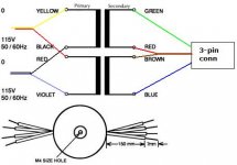
Ok here is where I am stuck. First the transformer hook up. I have the input side figured out but the out to the pre?? Series or parallel kinda lost there. Also the pin out of the pot? I searched all over for it and no luck. Also one other thing, do I need to change the gain on my BrianGT lm1875?? should have it up and running tonight. I'll try to post some pics. Thanks.🙂
On the gain question for your power amp, just leave it as it is. Later you may want to decrease it a little, but it should be just fine.
So, here a link to the wiring diagram for the trafo:
http://amveco.com/Miniature_Low_Profile_Transformers_2.htm
I meant to include this in the beta kits for those who bought the trafo, but, well, it's beta.
So you would wire it like this...
[edit] That's for 115V power. For 230V, you wire the two center primaries together, and run pwer to the two outside primaries.
Attachments
- Status
- Not open for further replies.
- Home
- Amplifiers
- Headphone Systems
- Digitally controlled preamp/headphone amp