I was trying to use that transformer in my DAC. However, 2 coupling MIT RTX 0.01uF caps sounded better. On the other hand, I have a transformer in my transport so I don't know how it affects the whole setup.
If yyou don't terminate them properly on BOTH ends, they probably will sound like crud.
You can use them on both ends. Again, if you do it properly.
You have to remember, not only did Harry and I do this stuff for 8-12 hours each day at work, then we came home and did more of it.
Jocko
You can use them on both ends. Again, if you do it properly.
You have to remember, not only did Harry and I do this stuff for 8-12 hours each day at work, then we came home and did more of it.
Jocko
Should have sounded better than that. If the TX transformer is as good as the ones Philips use.......pardon me whilst I get ill........, then that would explain a lot.
Jocko
Jocko
My setup is like that:
The transformer in the transport is the one from Sonic Frontiers. There are 75 ohm resistors in series with primary and secondary (I wasn't sure if they supposed to be in series or parallel with windings but that how the PCB was designed). In the DAC the receiver is CS8420. Since I have a transformer on the transport side I was trying to eliminate the coupling caps completely leaving only 75 ohm resistor to the ground, but CS8420 didn't lock then. Any explanation?
The transformer in the transport is the one from Sonic Frontiers. There are 75 ohm resistors in series with primary and secondary (I wasn't sure if they supposed to be in series or parallel with windings but that how the PCB was designed). In the DAC the receiver is CS8420. Since I have a transformer on the transport side I was trying to eliminate the coupling caps completely leaving only 75 ohm resistor to the ground, but CS8420 didn't lock then. Any explanation?
Digital Transformer
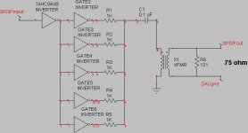
Transformers work best at tansport end. Here is a circuit using on CMOS hex inverter. I like a 50 to 100V polypro cap. High voltage caps have too much inductance. Jocko?
Transformers work best at tansport end. Here is a circuit using on CMOS hex inverter. I like a 50 to 100V polypro cap. High voltage caps have too much inductance. Jocko?
Thanks Harry.
The output resistor is 121ohm? When using that setup can I remove coupling caps at the DAC input. I tried to do it before, but without caps CS8420 didn't lock, why?
The output resistor is 121ohm? When using that setup can I remove coupling caps at the DAC input. I tried to do it before, but without caps CS8420 didn't lock, why?
Digital driver
The transformer driver goes in the CD transport. The resistor after the transformer is 121 ohms or 120ohms depending on 1% or 5% values. It is part or the attenuation network for the driver and also buffers the leakage inductance of the transformer to provide good back termination impedance of 75 ohms 1000/5 in parallel with 120 ohms. Leave the caps on the inuts of the Crystal receiver. YOU WANT ABSOLUTELY NO DC IN A PULSE TRANSFORMER.
The transformer driver goes in the CD transport. The resistor after the transformer is 121 ohms or 120ohms depending on 1% or 5% values. It is part or the attenuation network for the driver and also buffers the leakage inductance of the transformer to provide good back termination impedance of 75 ohms 1000/5 in parallel with 120 ohms. Leave the caps on the inuts of the Crystal receiver. YOU WANT ABSOLUTELY NO DC IN A PULSE TRANSFORMER.
Digital driver
The transformer driver goes in the CD transport. The resistor after the transformer is 121 ohms or 120ohms depending on 1% or 5% values. It is part or the attenuation network for the driver and also buffers the leakage inductance of the transformer to provide good back termination impedance of 75 ohms (1000/5 in parallel with 120 ohms). Leave the caps on the inputs of the Crystal receiver. YOU WANT ABSOLUTELY NO DC IN A PULSE TRANSFORMER. I believe that they are there because the inputs are biased at half the supply voltage. I may post in input buffer circuit for the Crystal if Jocko will work with me on it. The Crystal likes to see logic level signals at it's inputs for best sound. The transformer sounds best when used at transport end, it is quite tweaky to get the impedance match with the transformer at the DAC end which is why I like a differential buffer at the DAC digital input. When using a transformer, there are further tweaks possible for input circuits to help get better CMRR. The combination of the two circuits is quite magical when done correctly. Doing the interface correctly keeps RF noise from the transport out of your DAC and everyone would agree that that is a good thing!
You actually could use a 0.047uF cap or a regular 74HC04 for this circuit with no problems. Avoid 74AC logic and other fast logic for digital audio. It overshoots and creates EMI and sounds bad. Several digital audio designers have not quite figured this out yet.
H.H.
S/PDIF driver suggestions
Two technical issues with the '04 xfmr driver relating to my obsession with jitter:
1] As Jocko [are we Devo] et al have pointed out, part of the art is matching the xfmr; and the critical transitions, which define the edges of the waveform are essentially a transient high impedance state of the CMOS/TTL driver. When it switches, all bets are off...and the edge is when we also need the impedance matching. So, a class A *linear* driver is usually better, keeps the impedance more constant [one of my fave oxys] during transitions.
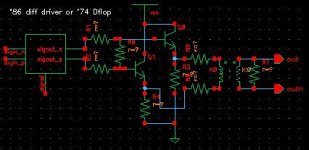
B] Single ended CMOS/TTL drive is way too power supply sensitive: any power supply shift will shift the launch point and introduce jitter, including at hard to filter low frequencies. Try a balanced scheme, either using a[n] '86 with two sections wired out of phase/polarity for matched delays; or preferrably a '74 using q and qbar outputs being fed a clean clock for registering/reclocking.
I think it was Ed Meitner who gets credit for first suggesting the obvious: hook up a highish gain AC coupled amp to a digital supply rail and listen. Watch the gain, save your hearing for music. You will hear strange gremlins, correlated to the music signal. You do not want any critical timing signal referencing these gremlins.
Hopefully the attached sch is more readable this time. The r's in the sch depend on the implementation and should be experimented with. You may need a big blocking cap in series with the primary. The supply for the '86 or preferrably '74 should be clean and quiet. The CMOS/TTL driver "sees" the same load for each direction of the transition, and the emitter resistors can be set in conjunction with the transformer and load resistors to put the transistors in constant power mode, ie the transistors have the same i*v for each state, hi/low. The lack of thermal tails at this null point is audible, unless your name is J. Hirsch...
If you really want to get trick as the phrase goes, use a 6111 dual triode pencil tube with a 15 or 30 volt supply in place of the transistors. You would have the only tube drive transport on the block.😎
The 84xx rxp and rxn inputs are self biasing, and can handle many volts of signal. Try hooking the secondary of the xfmr with the load matching resistor directly across them with no ground reference and no caps. It may work in your system, it may not.
Enjoy,
WMS
Two technical issues with the '04 xfmr driver relating to my obsession with jitter:
1] As Jocko [are we Devo] et al have pointed out, part of the art is matching the xfmr; and the critical transitions, which define the edges of the waveform are essentially a transient high impedance state of the CMOS/TTL driver. When it switches, all bets are off...and the edge is when we also need the impedance matching. So, a class A *linear* driver is usually better, keeps the impedance more constant [one of my fave oxys] during transitions.
B] Single ended CMOS/TTL drive is way too power supply sensitive: any power supply shift will shift the launch point and introduce jitter, including at hard to filter low frequencies. Try a balanced scheme, either using a[n] '86 with two sections wired out of phase/polarity for matched delays; or preferrably a '74 using q and qbar outputs being fed a clean clock for registering/reclocking.
I think it was Ed Meitner who gets credit for first suggesting the obvious: hook up a highish gain AC coupled amp to a digital supply rail and listen. Watch the gain, save your hearing for music. You will hear strange gremlins, correlated to the music signal. You do not want any critical timing signal referencing these gremlins.
Hopefully the attached sch is more readable this time. The r's in the sch depend on the implementation and should be experimented with. You may need a big blocking cap in series with the primary. The supply for the '86 or preferrably '74 should be clean and quiet. The CMOS/TTL driver "sees" the same load for each direction of the transition, and the emitter resistors can be set in conjunction with the transformer and load resistors to put the transistors in constant power mode, ie the transistors have the same i*v for each state, hi/low. The lack of thermal tails at this null point is audible, unless your name is J. Hirsch...
If you really want to get trick as the phrase goes, use a 6111 dual triode pencil tube with a 15 or 30 volt supply in place of the transistors. You would have the only tube drive transport on the block.😎
The 84xx rxp and rxn inputs are self biasing, and can handle many volts of signal. Try hooking the secondary of the xfmr with the load matching resistor directly across them with no ground reference and no caps. It may work in your system, it may not.
Enjoy,
WMS
Attachments
Transformer interface
Yep........ I figured some " expert "was going to second guess me on this one. Yes you need good supply for the driver IC, no suprise. Yes the output impedance is in transition during switching but is stable by the time the reflection gets back to the source driver. I have used several video buffers but have not found a sonic improvement over logic based drivers. There is also an impedance difference between low and high impedance states due biasing on the output stage of a video buffer. I have used the 74HC86 as a phase inverter for driving balanced digital out for AES/EBU interfaces. It works real well. Jocko said this circuit was too good to give away for free! It is an inexpensive and very good way too do this driver.
I spent 3 years playing with the digital interface for what ever that is worth.
P.S. YOU WANT ABSOLUTELY NO DC IN A PULSE TRANSFORMER. This applies to output or input side of the interface. Direct connection to the Crystal receiver inputs will put current in the transformer due to offset voltages and screw up the sound.
Power supply noise
"hook up a highish gain AC coupled amp to a digital supply rail and listen." That is what oscilloscopes and spectum analysers are for. Noise at over a megahertz is hard to hear.
"hook up a highish gain AC coupled amp to a digital supply rail and listen." That is what oscilloscopes and spectum analysers are for. Noise at over a megahertz is hard to hear.
Could not have said it any better myself. Only problem is if you keep giving away designs like that, how are we ever going to keep selling them empty-shell high-end comapnies.
'74 flip-flop, eh? Ever hear of prop delay?
And you better buffer the input of those wretched 84XX receivers.
Jocko
'74 flip-flop, eh? Ever hear of prop delay?
And you better buffer the input of those wretched 84XX receivers.
Jocko
Jocko, do you have an opinion on the TI DIR1701/DIR1703? I have see you lambast the Crystal parts on many an occasion ^_^ but what alternatives do we have? Is there any monolithic IC/IC+buffer that you like for a reciever?
The reason I hate them so much is because they have a Schmitt trigger input stage. Put a buffer between it and the line, and they are fine.
Hard to say which ones work, and which ones don't without actually hooking them up. Helps to have A TDR, which I do. Believe it or not, the lousy Yamaha RX chip everyone hated so much actually has low reflections.
I prefer a linear stage, properly loaded to 75 ohms RESISTIVE. Layout and cable parasitics need to be addressed.
I'll lookat a data sheet on the TI parts to see if it gives any clues as to how it might work.
Jocko
If only I had a TDR...and a distortion analyzer...and a wideband spectrum analyzer..and...and...

TI DIR1701
Data sheet shows CMOS input, and receive circuit external. Looks good, easier to buy and implement than Crystal. Is that what you were hoping to hear. Maybe I'll buy one and mess with it.
Sorry everyone else does not have my lab, but that is what it takes to make this stuff work properly.
Remember, bits is bits.........it is perfect.......forever!
Jocko
I've sampled 1701 and 1703, but only built a circuit with the former. TI's sample program is pretty fast, so if you have the time it should be easy to get ahold of one.
- Status
- Not open for further replies.
- Home
- Source & Line
- Digital Source
- Digital transformer