Don't wory I'm like you too, see pictureI do not understand completely: I connect the crocodile clip of my scope probe to where, and the probe itself to the same point...? Please explain again for me, I am no expert, only amateur diyer: how do you suggest to connect the scope to the noisy GND?

For checking the ADDR1 issue it might be quicker to remove both R6 and R7 and replace R7 with the 10k resistor and leave R6 unpopulated. Of course, also connecting the bridge to 5VDC.
There is no issue with my adress jumpers: one board is configured as 0 and the other one as 1. Works as shown in my schematic by just opening and closing the solder jumpers. No need of swapping resistors around 😀
I’d put the Muses before the Naim (Muses out to ‘IN’ on left of your schematic in 296 above), like it’s done in the Iron Pre: Input Selection > Volume Attenuation(Muses) > Buffer > Gain(xfmr on the IP).
That's not the way a Naim chain works. As mentioned I have a working Muses board in another preamp (the same type of dual railed Naim).
I will do some tests with the gain pins, hope that will sort the noise. I was thinking that the cap is decoupling the gain circuit inside the Muses and the output to the external opamp is balanced, but it seems I got it totally wrong...
And there shouldn’t be. That’s ok when using only two pin jumper. I also use this configuration and I’m also more rude because I don’t put the 100ohm resistor 🙂There is no issue with my adress jumpers
A more elegant way to accomplish the same result is to use a three pin jumper.
I will do some tests with the gain pins, hope that will sort the noise. I was thinking that the cap is decoupling the gain circuit inside the Muses and the output to the external opamp is balanced, but it seems I got it totally wrong...
I’m quite confident that if you remove C11,12,15,16 and left unconnected PIN 3,4,13,14 taking signal out from PIN 6 and 11 and signal ground from L&R REF you should sort the noise issue.
No progress so far. The noise stays perfectly the same whatever I do. What I tried so far:
I removed the caps and left the pins floating, no difference. Also tested it with all 6 grounded: same.
Yes - no difference.
Yes, no difference.
Added 100k to ground before and behinde the Muses volume - no difference.
Other source, open inputs, shorted inputs - all no difference. Well, the only difference was: with shorted inputs the volume change clicks between 0dB and -10dB disappeared completely. But the noise stayed.
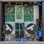
I struggled to make the noise visible at my Rigol scope. Only at the speaker output of my power amp I can make it visible:

This is with the Muses turned up to full volume (0dB) when it sounds silent. You can see a 40kHz wave with a peak to peak amplitude of 260mV. And this is with the noise, when the Muses is set to -20dB:

Seems like some kind of oscillation...? But where does it come from?
One possibility - given that the noise lessens from -10dB and is gone at 0dB - is an issue with the way you handle the Muses gain circuitry. FWIW, I left pins 2, 3, 4, 13, 14 and 15 totally floating - no connection to anything.
I removed the caps and left the pins floating, no difference. Also tested it with all 6 grounded: same.
Did you try the conventional power supply hookup as per the datasheet? No separation of power supplies.
Yes - no difference.
I’m sure you tried connecting ALL grounds together🙂.
Yes, no difference.
What is the input impedance of the Naim clones? Don’t think that a likely cause but…
Added 100k to ground before and behinde the Muses volume - no difference.
And only other thing I can think of at present is your source. Input impedance of the Muses is 20k ohms - which should be fine but, grasping at straws, did you try an alternate source?
Other source, open inputs, shorted inputs - all no difference. Well, the only difference was: with shorted inputs the volume change clicks between 0dB and -10dB disappeared completely. But the noise stayed.
I struggled to make the noise visible at my Rigol scope. Only at the speaker output of my power amp I can make it visible:
This is with the Muses turned up to full volume (0dB) when it sounds silent. You can see a 40kHz wave with a peak to peak amplitude of 260mV. And this is with the noise, when the Muses is set to -20dB:
Seems like some kind of oscillation...? But where does it come from?
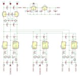
Update: I checked everything about oscillation, isolated the regulators and removed all 100uF caps. After messing around with the boards the whole day I understood that signal ground needs to be separated from power ground, but not as I did in my previous schematic - so I cut some tracks and re-arranged GND. I fitted 10uF SMD tants to where the 100uF caps were, and the noise is finally gone. Many thanks for all the support! Attached my final schematics and the modded boards:
Attachments
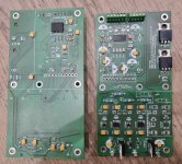
Sorry, I was a bit off topic, but to get back to topic I attach my kicad and gerber files. The project is quite flexible, there are a lot of solder jumpers that can be used to play around, and the PCB can be cut in pieces. Thanks again and hope it helps for future attempts!
Attachments
This might be slightly off topic, but I am wondering if I could use the gain feature of the Muses like this:

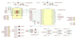
The schematic shows the Naim style gain stage that I am using in my preamp. The Muses72323 attenuator sits at the input of this circuit (and there is another buffer before the Muses volume). The gain feature of the Muses I thought to connect like this:

Is it a good idea to wire in pin2/3/4 of the Muses chip into the Naim circuit and control the gain like that?
The schematic shows the Naim style gain stage that I am using in my preamp. The Muses72323 attenuator sits at the input of this circuit (and there is another buffer before the Muses volume). The gain feature of the Muses I thought to connect like this:
Is it a good idea to wire in pin2/3/4 of the Muses chip into the Naim circuit and control the gain like that?
The Muses likes to use a very high load impedance, preferable bigger than 470k. It's noted in the datasheet IIRC.
Is this the case in your circuit?
Is this the case in your circuit?
I can't find the information about load impedance being 470k (or bigger). The only mention of 470k I can see in the schematic at the output: but I am asking about the gain feature of the Muses chip. I thought this has nothing to do with the load on the attenuator...?
Just checked, indeed, only in datasheet of Muses 72320 they give info on this, see page 10 +11. Reading between the line => they propose 470k.
Thanks, found it! It seems to me the 470k is a current biasing resistor for the opamp input. Do I need it at all with my discrete gain stage...?
It's been a long time 🙂Hardware works (well, the second PCB revision is definitely required), time to work on the firmware 🙂
View attachment 1239793
SSD1306 display, encoder or potentimeter control. Or it can be controlled by external MCU, the module can be switched to I2C slave mode.
1db steps, max attenuation is -63dB.
The library originally created by Christoffer Hjalmarsson in use to control the MUSES72323 volume controller doesn't include a routine for adjusting the gain section (there is only a non-functional placeholder). This library has now been modified. Changes include:
- Increase clock speed to align with MUSES72323 data sheet of 1MHz (- 200KHz margin)
- Amendment of volume_to_attenuation routine to align with MUSES72323 settings
- Implement setGain function to provide option to adjust gain section between 0dB and +21dB in 3dB steps
The latch pin was already included in the original library by Christian and is part of the input criteria for the Muses() construct routine. JRC call the pin on the MUSEs chip LATCH but most other chips tend to call it CSbar.Nice! But how can we specify the latch pin?
How to specify to the construct routine which pin of the microcontroller will drive it is something like this in the main.ccp file:
// define preAmp control pins
#define address_Muses 0
#define muses_CS 10
// preAmp construct
Muses72323 Muses(address_Muses, muses_CS);
This passes the relevant data into the Muses72323(address_t chip_address, pin_t latch) routine in 72323.cpp
- Home
- Amplifiers
- Pass Labs
- Digital Control of Attenuation – Repository for DIY