Yes, the muses chip will only see "dirt" on the same SPI if the display does some stuff while the muses is not doing anything... BTW I am trying to understand how the internal isolation inside the muses works. The SPI lines and the +5V with it's GND is isolated from the rest, so external isolation does not seem to be necessary unless you feed the +5V from the analog +15V supply and share GND. If I understand the datasheet correctly the muses chip has a lot of separate power inputs:

At the clean side of the islolator we could have as many as 5 separate 0V lines for digital, analog and signal return (like in a mono DAC chip). Power decoupling could look like this:

We could feed the muses from 7 voltage regulators or use the 7805 to get +5V.
So the question is: how much isolation and separate power rails are needed if sound quality is paramount?
At the clean side of the islolator we could have as many as 5 separate 0V lines for digital, analog and signal return (like in a mono DAC chip). Power decoupling could look like this:
We could feed the muses from 7 voltage regulators or use the 7805 to get +5V.
So the question is: how much isolation and separate power rails are needed if sound quality is paramount?
Yes, I tend to agree re not needing the isolator if you are using a separate 5VDC rail for the Muses digital supply. Definitely need it if taking the digital 5VDC from the +15V analog rail. In my case I found a dual-rail 5VDC supply (7805) which I hadn't remembered I had so opted to use that. And having two rails to play with said 'Why not use the isolator as you have a spare rail'. So one rail for the 'dirty' side - for the ESP32, ADuM 1300 VDD1 and various other necessities of my particular implementation - and the second rail for the clean side of the isolator.
Interesting approach to separating the 15V supplies. My take is that the "D_V" pins aren't shown on the datasheet as actually connected to the isolated digital logic section so should be fine being supplied by the analog 15V as shown by the datasheet. They may not actually be seeing any sort of 'digital' signal internally. Can't see Muses stopping short of suggesting separate rails if those pins posed any threat to the analog section. But that's just my non-EE take 🙂.
Typo on the pin 16 input voltages on the Adum and Muses?
In my implementation I'm not using the gain on the Muses so opted to ground all the pins between 1 and 16 (except for 6, 11 and 16 obviously) to the GND on the Iron Pre - which has an NTC to chassis ground.
Like the filtering, especially on the digital 5V! If I didn't already have my Muses boards I'd steal it!!!
OK, I updated the code and made it possible to freely specify all pins in the soft-SPI version (Skylar88, you might want to add a link to the first post).
Done.
Just to report: I made a PCB with separate regulators for each supply that is shown in #281. So 3x +15V regulators, 3x -15V and a 7805 for the clean side of the isolator. Signal-GND and power-GND need to be connected together at one point. It works and sounds great.

As soon as the boards are fitted into my preamp I will report with some pictures 😎
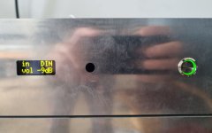
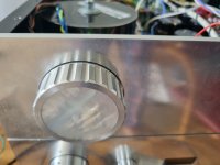
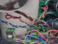
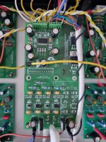
Here are some pictures - not finished yet, but already working (note the self made volume knob with the mother of pearl inlay). I can hear that it sounds way cleaner than my previous relay attenuator that was in the preamp before, but I have permanent noise on both channels, please help with that!
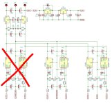
The Muses PCBs are configured for mono (it's a dual mono preamp), so 2 PCBs on top of each other, hence the non populated areas (crossed out in red on the schematics). I tested the Muses PCBs outside the preamp, they work fine, also I tested to use them in stereo mode etc. and tried many earthing topolgies, but the noise did not change at all. It sounds like a white noise and is independent from volume. Only in the loudest range between -10dB and 0dB it starts to reduce. At 0dB it's totally gone, but the last few steps I hear distinct clicking when chaning volume (louder than with the former relays). No clicking at all with less loud settings (I program full dB steps). The noise is loud enough to be heard during music play. I wonder if it's some kind of impedance mismatch between the preamp stages and the Muses chip? My other preamp (similar Naim clone circuits) do not have that noise, and my first Muses test-PCB works well in there. So I struggle to understand what's wrong here... Any hints much appreciated!
The Muses PCBs are configured for mono (it's a dual mono preamp), so 2 PCBs on top of each other, hence the non populated areas (crossed out in red on the schematics). I tested the Muses PCBs outside the preamp, they work fine, also I tested to use them in stereo mode etc. and tried many earthing topolgies, but the noise did not change at all. It sounds like a white noise and is independent from volume. Only in the loudest range between -10dB and 0dB it starts to reduce. At 0dB it's totally gone, but the last few steps I hear distinct clicking when chaning volume (louder than with the former relays). No clicking at all with less loud settings (I program full dB steps). The noise is loud enough to be heard during music play. I wonder if it's some kind of impedance mismatch between the preamp stages and the Muses chip? My other preamp (similar Naim clone circuits) do not have that noise, and my first Muses test-PCB works well in there. So I struggle to understand what's wrong here... Any hints much appreciated!
Attachments

Last edited:
Try put digital ground each by each pcb trought 100nF to the case and case is hope earthed. I'm practicing right now special care for gnd lines while designing pcb, it goes to the star ground at one point to the power supply output capacitor. If you hear noise in most case your pcb design is not very good, and those wires around is also not very good.
Last edited:
Thanks! Digital DNG from isolator dirty side goes to digital PSU. If I disconnect digital GND from the Muses PCB the noise does not change at all. Shall I add the 100nF (not 100pF?) to the existing connection to GND? Chassis is grounded of course. Wiring is not fineshed yet, some wires are still crocodile clips.
My preamp was totally silent with the stepped relay attenuator. And the Muses I also use in another preamp that is perfectly silent...
My preamp was totally silent with the stepped relay attenuator. And the Muses I also use in another preamp that is perfectly silent...
Last edited:
Nice volume knob indeed!! And boards.
Re the noise, when you say you tested the PCBs ‘outside the preamp’ and they work fine does that mean no noise on another audio amp with the same source?
One possibility - given that the noise lessens from -10dB and is gone at 0dB - is an issue with the way you handle the Muses gain circuitry. FWIW, I left pins 2, 3, 4, 13, 14 and 15 totally floating - no connection to anything.
Did you try the conventional power supply hookup as per the datasheet? No separation of power supplies.
I’m sure you tried connecting ALL grounds together🙂.
What is the input impedance of the Naim clones? Don’t think that a likely cause but…
And only other thing I can think of at present is your source. Input impedance of the Muses is 20k ohms - which should be fine but, grasping at straws, did you try an alternate source?
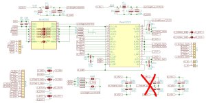
I haven’t had my morning C&C (coffee and constitutional) yet so am subject to correction here but something struck me as odd about your ADDR0 and ADDR1 schematic.
The way it is drawn the pull-ups will be grounded regardless of whether you apply 5VDC to set pin 30 high or not.
Also, although not relevant to your issue, there’s no need to make provision for pulling pin 31 up as, in a stereo balanced implementation, you only need address 0 and address 1 and both configurations require pin 31 to be grounded.
My preamp was totally silent with the stepped relay attenuator. And the Muses I also use in another preamp that is perfectly silent...
Is the noise not perhaps coming from the power supply to the Muses and MCU?
Am I correct that C1 and C2 are feedthrough capacitors? It's reminiscent of @Mark Johnson's AmyAlice filter, although not exactly similar.
My new board (still unbuilt) will use an AmyAlice filter which is incorporated onto the separate psu board. It was added to sleep better, although the current board is virtually quiet without it and using a Hi-Link smps without any filter.
Shall I add the 100nF (not 100pF?) to the existing connection to GND? crocodile clips.
more or equal to 100nF + 1M resistor in paralel, in my case I had similar noise and 1uF helped to eliminate all noises. Now I'm practic star gnd. The best thing to do while designing pcb is having star ground (ref gnd) so power gnd, signal gnd, digital gnd... is to be always separately drawn, connected at one point at ref gnd, that way all the problems is omited in relation to gnd isues. Four layer pcb, top layer signal gnd, inner1 gnd, inner 2 dc line paralel to inner1 line, and bottom layer for anything else depend on design, than huge plane on all layers is in connection to refgnd where all other gnds is connected in that star point. Special care to signal layer and allso inner1 layes, in my case inner1 is gnd layer is routed excatly the same as inner2 and inner1 lines gives the same time an shield to the dc inner2 layer. Capacitors, big plane must be canaled so that all the current goes trought capacitor first always, and not for it to be a short path trought something else for example trought your muses for example. Gnd is a very tricky thing, and if you use something asymetric like an flyback regulator and you getting isue trought gnd : ) Test your gnd noise with osciloscope, connect crocodile and pipe to the same point on your gnd, if you see noise than you know what to do : )
Last edited:
An example for canaling big plane so that all the current goes trought capacitor and not trought something you no want https://www.diyaudio.com/community/attachments/img_2204-jpg.1273447/
Your wires around, nothing else but an set of antennas communicating with each other, ok for first test design but for final design do it on single pcb. Torus transformers must have an metal barrier so that it not emit noise to pcb...etc
Last edited:
Many thanks for all the input! I will do my homework but some points I didn't fully understand, so I will commend below:
I thought pins 3,4,13,14 should be grounded as in Meldanos schematic. In my first build I don't have the caps populated, so it could well be the reason - especially as I use pins 3 and 14 as signal-GND. I will play around with the gain handling - but wanted to make sure first that I did not misunderstand something...
I double checked, and do not understand: I thought I have both pins pulled low with the big resistors, and the jumpers pull them high through small resistors. As I wanted to test various addresses I populated both pins so that I can easily open and close the solder jumpers to set the address.
The MCU is fed by an extra 5V PSU, and on the MCU board there is a 3V3 regulator that supplies the dirty side of the isolator. I am certain that the power is fairly clean, but I was thinking that the isolator would eleminate noise pollution from the digital PSU in any case. The analog circuts have their own PSUs and regulators.
Yes. Probably overkill...
I do not understand completely: I connect the crocodile clip of my scope probe to where, and the probe itself to the same point...? Please explain again for me, I am no expert, only amateur diyer: how do you suggest to connect the scope to the noisy GND?
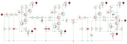
I attached the schematic of the preamp. The Muses volume sits between the buffer and the gain stages:
One possibility - given that the noise lessens from -10dB and is gone at 0dB - is an issue with the way you handle the Muses gain circuitry. FWIW, I left pins 2, 3, 4, 13, 14 and 15 totally floating - no connection to anything.
I thought pins 3,4,13,14 should be grounded as in Meldanos schematic. In my first build I don't have the caps populated, so it could well be the reason - especially as I use pins 3 and 14 as signal-GND. I will play around with the gain handling - but wanted to make sure first that I did not misunderstand something...
The way it is drawn the pull-ups will be grounded regardless of whether you apply 5VDC to set pin 30 high or not.
I double checked, and do not understand: I thought I have both pins pulled low with the big resistors, and the jumpers pull them high through small resistors. As I wanted to test various addresses I populated both pins so that I can easily open and close the solder jumpers to set the address.
Is the noise not perhaps coming from the power supply to the Muses and MCU?
The MCU is fed by an extra 5V PSU, and on the MCU board there is a 3V3 regulator that supplies the dirty side of the isolator. I am certain that the power is fairly clean, but I was thinking that the isolator would eleminate noise pollution from the digital PSU in any case. The analog circuts have their own PSUs and regulators.
Am I correct that C1 and C2 are feedthrough capacitors?
Yes. Probably overkill...
Test your gnd noise with osciloscope, connect crocodile and pipe to the same point on your gnd, if you see noise than you know what to do : )
I do not understand completely: I connect the crocodile clip of my scope probe to where, and the probe itself to the same point...? Please explain again for me, I am no expert, only amateur diyer: how do you suggest to connect the scope to the noisy GND?
What is the input impedance of the Naim clones? Don’t think that a likely cause but…
I attached the schematic of the preamp. The Muses volume sits between the buffer and the gain stages:
Attachments
Last edited:
Yes. Probably overkill...
Having a good filter can never be overkill. Have a look at @Mark Johnson's AmyAlice filter which also employs feedthrough capacitors. From his description, I gathered that the filter should be properly designed for best effect.
@jpk73
if I understand correctly your schematic, there are some critical issue in it.
Pin 2,3,4 and 13,14,15 must be used ONLY if you have a OPAMP as gain device at the Muse output.
Then you can control the gain of this OPAMP with the Muse itself.
If you are not using this feature Pin 2,3,4 and 13,14,15 must be tied to ground or left floating.
Pin 4 cannot be “L_OUT-“ and Pin 13 cannot be “R_OUT-“
I’d put the Muses before the Naim (Muses out to ‘IN’ on left of your schematic in 296 above), like it’s done in the Iron Pre: Input Selection > Volume Attenuation(Muses) > Buffer > Gain(xfmr on the IP).
At the same time, I’d try both of your boards configured as ADDR 0, that is, with NO 5VDC connection.
I’d also try lifting 2, 3, 4, 13, 14 and 15 so they float.
At the same time, I’d try both of your boards configured as ADDR 0, that is, with NO 5VDC connection.
I’d also try lifting 2, 3, 4, 13, 14 and 15 so they float.
- Home
- Amplifiers
- Pass Labs
- Digital Control of Attenuation – Repository for DIY