That's strange... I always use an USB isolator if I leave the MCU connected to the PC while testeing the audio device... And what exactly did blow your Muses IC?
Do you mean noise on the the digital lines between the MCU and the Muses IC could inject noise into the analog signal? In that case a simple line buffer should suffice, such as a HC125 or so?
note - in case of what's subject of this thread - I'm not expecting problems from digital circuitry of Muse itself, rather of what's actually governing Muse
Do you mean noise on the the digital lines between the MCU and the Muses IC could inject noise into the analog signal? In that case a simple line buffer should suffice, such as a HC125 or so?
Last edited:
Do you mean
I mean any MCU is better to have "isolated" PSU from audio circuitry
Which way is that going to be, don't care, as long it is effective
I mean, "isolated" is sort of deceiving term, let's say "properly anchored", and my choice is to anchor it to safety GND/chassis
that way lesser possibility that MCU PSU start wandering around, searching for anchor by itself
of course, for that, MCU PSU needs to be separate/galvanically isolated from audio circuitry

Thanks for clarifying. In #124 the isolator isolates digital lines and 5V but introduces a switching supply I guess? I agree a separate digital PSU is the way to go, and if GND goes through chassis (and resistors) it will be enough isolated it seems...
EDIT: it seems there is also a regulator, so digital power only poweres the isolator IC...?
EDIT: it seems there is also a regulator, so digital power only poweres the isolator IC...?
Last edited:
@jpk73
As you know Muse need two different voltage. A dual power (+/-15) for analog section and a 5V power for it's digital section
The three IC's that you can see in my board are the Muse itself, a 3ch digital isolator and a three terminal voltage regulator. This ic is not a switching, but just an old classic linear voltage regulator.
Here is a simple block diagram to show how the board is made.
check also post #99 for more info.
Michele
Attachments
Thanks for sharing the block diagram! It's very helpful. Only my question remains: is DGND and AGND of the Muses IC on the clean side of the isolator tied together?
I use PAI140M30 as digital isolator in my project. I work fine form now.@jpk73
As you know Muse need two different voltage. A dual power (+/-15) for analog section and a 5V power for it's digital section
The three IC's that you can see in my board are the Muse itself, a 3ch digital isolator and a three terminal voltage regulator. This ic is not a switching, but just an old classic linear voltage regulator.
Here is a simple block diagram to show how the board is made.
check also post #99 for more info.
Michele
I'm finishing to implement the NEC IR decoder in the main code.
https://www.diyaudio.com/community/threads/my-muses-72320-volume-control.400831/#post-7484106
Attachments
Last edited:
Thanks @lalaina
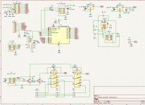
I have a question: In your schematic above, why are pins 21, 29, 30, 31 & 32 tied to GNDA? I thought those pins were part of the digital block and should ideally be kept on the "clean side", to quote @mvaldes.
It's nice to see that there are "refinements" in recently posted circuits, which were not present in some older Muses schematics. It looks like the circuits are "maturing" or evolving in sophistication.
I'm still working on the circuit of my Muses board and I'm "stealing" some ideas from recent posts.
I had a play with an ESP32, screen and an encoder. It is possible to use the encoder button in three ways. A simple press, a long press and a double press. I was just doing the user interface coding and used a single press to enter a menu, double press for standby and long press for mute. I also played with the WiFi and made a very simple web app to use my phone as a remote, the volume control was very slow and needed some work. I also managed to integrate my PiCorePlayer by using TPC to read or set the volume and get track info, I tried to get the album art to display on the screen but either the ESP32 was not powerful/fast enough or my coding was not up to it and could not get it to work.
Started playing about with a teensy MCU and a touchscreen, I think the screen was duff as I could not make it display. The touch worked ok. I expect I will have another go with the teensy 4.1 with touchscreen, IR remote and encoder.
Not played with any digipots or relays yet but have a couple of MAX5408 that I want to try out that might be good for SE and balanced.
I had a play with an ESP32, screen and an encoder. It is possible to use the encoder button in three ways. A simple press, a long press and a double press. I was just doing the user interface coding and used a single press to enter a menu, double press for standby and long press for mute.
Excellent idea. I might adopt that functionality. I may even ask for your code to detect the various encoder press states, as I'm also using ESP32.
Thanks for the feedback. Appreciated!
You are right but I can't separate analog GND and digital gnd withe the muses. I can't find a way. I' have already blowing one muses when trying to do.
Have a look at the schematic I posted yesterday in post#130. It works for me and is the only way I don't blow up expensive Muses chips. 🤣
PS: In that schematic you can clearly see that pins 29 - 32 are part of the digital block.
Edit: Here's a thought on what could also be a cause of blown chips. The Muses pins are so close together (0.65mm), as I'm sure you know. It's possible that solder bridges can form without one knowing it. I use a microscope to inspect from all angles, especially behind the pins under the plastic body.
Last edited:
I will have a look for the button press code. When a button press was detected I think I did some IF ELSEs, tried to detect a long press then a double and that left a single press.
unsigned long singleMillis, doubleMillis;Excellent idea. I might adopt that functionality. I may even ask for your code to detect the various encoder press states, as I'm also using ESP32.
Thanks for the feedback. Appreciated!
singleMillis = millis();
if (digitalRead(PUSH_BTN) == LOW) {
delay(20);
do {
} while (digitalRead(PUSH_BTN) == LOW);
if ((millis() - singleMillis) > 600) {
encButt = 3;
return; // long press
} else
doubleMillis = millis();
delay(20);
while (digitalRead(PUSH_BTN) == HIGH) {
if ((millis() - doubleMillis) > 180) {
lastActivity = millis();
encButt = 1;
return;
} // single press
}
encButt = 2;
return;
}
encButt = 0;
return;
I hope this might be of some help. In my code I had a variable the for encoder's button and movement. At the beginning of each main loop I would check the inputs (remote, encoder, buttons etc) and either do something or nothing.
Thank you both.
The library that @jpk73 linked looks quite comprehensive, but is for Arduino. It'll have to be ported to ESP32 before I can use it. The debounce claim sounds very attractive.
Edit: You were posting the code while I was typing, @ElliJ.
I'd like to try your code, but the delay() pauses will really screw up the other functions in my sketch. Can it be made to work without delay()?
Last edited:
Should be easy: if you look through the code you will not find much that ist platform dependent. I use this code on attiny, due, teensy, avr...
I had a quick look and I think you are right. Shouldn't be too difficult to use it on ESP32.Should be easy: if you look through the code you will not find much that ist platform dependent. I use this code on attiny, due, teensy, avr...
Yes, and it's the most elegant solution to debouncing and de-emi-ing buttons I ever came across, so I made that library out of the code shown in this hackaday article.
EDIT: I also have code for mechanical rotary encoders that usually bounce, if you need it I can post it here or upload it to Github.
EDIT: I also have code for mechanical rotary encoders that usually bounce, if you need it I can post it here or upload it to Github.
Last edited:
I used code for the encoder that ignored the bounce by checking the sequence. It worked perfectly with the cheap encoders. Here is the YouTube link:
- Home
- Amplifiers
- Pass Labs
- Digital Control of Attenuation – Repository for DIY