Hi,
I was thinking about something simple and came up with following design:
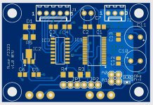
6 relays attenuator [0..-63dB]
Three options for control:
1. Potentiometer
2. Encoder
3. External MCU, via I2C
To enable it as standalone module, it can be configured as I2C master and output attenuation level to a display (I'm thinking about ssd1306 128x64 OLED)
Hardware works (well, the second PCB revision is definitely required), time to work on the firmware 🙂


Thanks!
In this revision I was thinking only about a display but IR is also possible, I'll add a connector in next revision.
Another option is to have a separate board with encoder+display+IR and a single cable to the attenuator board.
The MCU is CH32V003. I really liked it, easy to program and a lot of peripherals.
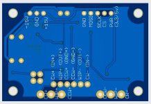
Other option - it's 34-pin but when did a couple extra pins stop prototypers 🙂?.....
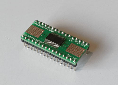
Here is my Muses72032 chip soldered to such an adapter board, ready to be plugged into a breadboard.
@Skylar88 - think I saw a mention of you dimming the Waveshare somewhere. Just confirming that it can use the BL.
After your Waveshare/ESP32 endorsement I might get an ESP32 and the Waveshare and see where it goes - they certainly seem affordable enough. I want a tape monitor as well as an AV passthrough that incorporates the L, R and Sub outs of an AV pre - being Greedy, of course - so some fun programming and PCB design ahead.
think I saw a mention of you dimming the Waveshare somewhere. Just confirming that it can use the BL.
Hi @derekr, Yes, I'm using the backlight (BL) to vary brightness. Just send a PWM value to the pin like this: analogWrite(ledPin, 220)
The ESP32 Devkit V1 is a good match with the Waveshare screen. It has plenty of RAM and speed to make very nice displays. Once you get yours working, I'll share some tips that I've learned with the screen. E.g. if you power the screen from the ESP32 like in the tutorials, there is an annoying second or two after startup when the screen is white, before it starts displaying whatever you're sending to the screen. I have found a way to let the screen stay black until the images get displayed. It's not as straight forward as one might think. Just sending a zero PWM value with analogWrite(ledPin, 0) to blank out the screen doesn't work. More later.
The IC Test Socket Programmer is a great solution to get started. 👍
You definitely want to use a breadboard to experiment with the Muses chips. The datasheets can be misleading, therefore you need to experiment to see what works and also what works best.
Last edited:
What exactly is misleading...? Can't we use just a proven schematic and make a basic layout and be sure not to cripple performance and SQ?
The two Muses chips that we are concerned with, 72320 and 72323 are quite versatile. It can be used in more than just one way; with and without gain opamps. If you follow the datasheets verbatim, you will build a stepped resistor attenuator (internal) with external gain opamps. There are two power sources needed: a binary +-15V supply for the audio section and 5V for the digital block.
For me, first deviation from datasheet: I'm not interested in adding gain, because I'm using the Muses with the Iron Pre, which already has gain. You need to study the datasheets to find out what connections and components are not needed if you don't want to use the gain part of the chip.
Second deviation from datasheet: The Iron Pre already has a beautiful and clean binary 15V shunt power supply designed by Zen Mod. And with his blessing, I've decided to use the latter to also power the audio section of the Muses. ZM's blessing came with a caveat/warning to mind the GNDs. He was right. When using the 15V of the Iron Pre, there is a problem when connecting all the GNDs in the datasheet, which incidentally connects the GND of the audio section to the GND of the data block.
As a "Muses rookie", I didn't know any of the above, and had to discover it the hard way, blown Muses chip and all. There are many Muses schematics floating around the Internet. Use any one of them blindly at your own peril. I guess, it depends on where and how you're going to use the Muses chip.
To illustrate what I mean, this is a tested and working circuit without the bells and whistles (opamps for gain) that are shown in the datasheet. Note how the GNDs of the digital block and the audio section are being kept apart.
While this is a working circuit, one may add refinements like a voltage regulator to get 5V from the 15V binary PSU for the digital block, as well as a digital isolator to ensure the power supply lines don't carry EMI that may contaminate the signal.
NB: Pin 16 connects to DGND, not AGND.

While this is a working circuit, one may add refinements like a voltage regulator to get 5V from the 15V binary PSU for the digital block, as well as a digital isolator to ensure the power supply lines don't carry EMI that may contaminate the signal.
NB: Pin 16 connects to DGND, not AGND.
Last edited:
Thanks a lot! Exactly what I am looking for. Can I reduce the input caps to say 10uF? And why are the 2 resistors marked in red with "caution"?
Last edited:
Oh, sorry about the input caps. I left it in although I'm not using any caps there! 😉 Feel free to omit them when using the Muses with an Iron Pre. It has been tested and I'm listening to it while typing this.
Maybe I should have added a disclaimer. The schematic above is only for use with the Iron Pre.
The "caution" came over from the datasheet. Those 2 resistors are quite important to protect the Muses chip. I'd advise to keep them in.
Maybe I should have added a disclaimer. The schematic above is only for use with the Iron Pre.
The "caution" came over from the datasheet. Those 2 resistors are quite important to protect the Muses chip. I'd advise to keep them in.
Join DGND and AGND? You're kidding, right? 
Are you using the Muses with an Iron Pre? Just so I know how best to advise you.
Are you using the Muses with an Iron Pre? Just so I know how best to advise you.
Last edited:
I intend to use it with a Naim clone that has in and out caps at the previous and following stages (buffer stage -> volume pot -> gain stage).
If you derive the 5V from the 15V supply the GNDs are joined somewhere. Hence I asked where they are joined best...
If you derive the 5V from the 15V supply the GNDs are joined somewhere. Hence I asked where they are joined best...
Last edited:
I don't know how the Naim clone handles GND. Maybe you don't need to split the two GNDs. There are many examples of Muses circuits where it's not split. But with the Iron Pre, where the audio signal GND is connected to the binary PSU GND, it is necessary to keep the GNDs separate. Do you homework and decide if it's necessary for you to split GNDs.No, I will use it with a Naim clone that has in and out caps at the previous and following stages (buffer stage -> volume pot -> gain stage).
Ok, fair enough. I previously mentioned a digital isolator. That's how you can join the GNDs without ill effect. Look at the ADUM130D0BRZ. It's a 3-channel isolator. In post#124 @mvaldes has shown how he uses that isolator. IC3 in the first picture is the ADUM130D0BRZ and if I'm not mistaken, IC2 is a NJM78L05UA-TE1 voltage regulator to get 5V from the 15V supply.If you derive the 5V from your existing 15V supply the GNDs are joined somewhere. Hence I asked where they are joined best...
it is necessary to keep the GNDs separate
not necessary but most welcome, at least for my OCD
in my concoctions, using Arduino to govern everything relays and everything visual and everything remote, all of that is powered from separate small 10VA Donut, and negative of that PSU is firmly bolted to chassis potential
Audio side - meaning Audio GND, each channel having 10-15R NTC to chassis
so, if something (harsh) goes, it goes to chassis/safety GND
yes, they are ............ as exactly they need to be
to fully avoid any possible interference, digital GND must be connected somewhere, not left floating in any way
and blackest black hole on disposal is Safety GND
note - in case of what's subject of this thread - I'm not expecting problems from digital circuitry of Muse itself, rather of what's actually governing Muse
Ok, let me share my experience - and remember I'm breadboarding, so I can make quick adjustments to the circuit if something doesn't work.
What I'm working with:
Muses72320 chip, Iron Pre with binary 15V supplying power to the Muses analog side. Signal input to Muses comes from Iron pre with signal GND connected to power GND of Iron Pre.
Observation:
If the analog/audio GND is connected to the digital block GND of the Muses (and MCU), the Muses doesn't want to change attenuation. When the GNDs are separate, everything works fine. That's what I'm basing everything on that I've posted today.
- Home
- Amplifiers
- Pass Labs
- Digital Control of Attenuation – Repository for DIY