Will be implemented in the next release.That's great. One other suggestion- until a formal calibration I would want it to default to dBFS since that is intrinsically "correct".
Could you be more specific, please?Having trouble connecting to DiAna software site.
Curious, I just opened it Index of /diana/ and downloaded the file. Perhaps your ISP is blocking it for some reason? You could try its IP: 72.29.88.138 and see what happens.
Here is a trace from my PC:
1 2 ms 1 ms 1 ms 192.168.29.1
2 10 ms 10 ms 9 ms 96.120.91.233
3 9 ms 8 ms 10 ms 96.110.177.221
4 10 ms 11 ms 28 ms be-215-rar01.santaclara.ca.sfba.comcast.net [162.151.78.193]
5 12 ms 12 ms 11 ms be-299-ar01.santaclara.ca.sfba.comcast.net [68.86.143.93]
6 12 ms 11 ms 19 ms lag-14.ear3.SanJose1.Level3.net [4.68.72.105]
7 77 ms 79 ms 81 ms ae-1-8.bar1.Orlando1.Level3.net [4.69.137.149]
8 77 ms 86 ms 77 ms HOSTDIME.bar1.Orlando1.Level3.net [4.31.179.146]
9 77 ms 78 ms 77 ms ae2.core1.mco.hostdime.com [67.23.229.201]
10 79 ms 77 ms 77 ms server.budgetwebsiteserver.nl [72.29.88.138]
I was doing some testing of my hardware and tried using DiAna on a 20 KHz tone measures at 192 KHz. The results are interesting and not far from the analog measurements except how are the harmonics above 80 KHz arrived at? The ADC has a brick wall by definition at 96 KHz. Are they inferred from the measured sample values (pretty trick)?
Attachments
Hi Demian,
Whether the harmonics above the Nyquist frequency are meaningfull or not depends on the properties of the ADC. In case of audio (delta sigma) ADC's, these harmonics are the result of noise and should be ignored. Only in case of a SAR ADC + a suitable sample & hold circuit and no anti-alias filter(i.e. an ADC designed for under sampling) these harmonics are meaningful. Please, also have a look at this post and the following replies.
Cheers, E.
Hm, I have re-read that discussion and still do not understand how undersampling can be applied to a NON-band-limited signal. The principle of undersampling is quite obvious https://www.eetimes.com/how-to-use-undersampling/ but any material about undersampling always stresses the applicability to a signal with frequency range fitting into the multiple of fs/2 - the signal spectrum must be band-limited to <n*fs/2, (n+1)*fs/2> before the AD conversion.
Hi Stuart,
I downloaded your distortion analyzer SW from download site. May I have password for zip file.
Thanks is advance.
Zsolt
I downloaded your distortion analyzer SW from download site. May I have password for zip file.
Thanks is advance.
Zsolt
still do not understand how undersampling can be applied to a NON-band-limited signal.
I think I understand the principle:
fundamental 20kHz, sampling fs 48kHz
H1: 20kHz -> 20kHz
H2: 40kHz -> 48 - 40 = 8kHz
H3: 60kHz -> 60 - 48 = 12kHz
H4: 80kHz -> 96 - 80 = 16 kHz
H5: 100 kHz -> 100 - 96 = 4kHz
H6: 120 kHz -> 120 - 120 = 0Khz - unavailable
H7....
Since the harmonics in this case do not overlap, finding their frequencies in the combined spectrum of all <(2n)fs/2, (2n + 1)fs/2> intervals is possible.
How would it work e.g. for 8kHz?
H1: 8kHz -> 8kHz
H2: 16kHz -> 16kHz
H3: 24kHz -> unavailable
H4: 32kHz -> 48 - 32 = 16kHz -> overlap
H5: 40kHz -> 48 - 40 = 8kHz -> overlap
Do I get it right?
I'm afraid some misunderstanding is going on. Admittedly, I have used the term "under sampling", but only to explain why it is possible -in principle- to reconstruct signals above the Nyquist frequency. But that doesn't mean DiAna works in the same way as the under-sampled AD conversion in an IF stage, for example.Hm, I have re-read that discussion and still do not understand how undersampling can be applied to a NON-band-limited signal. The principle of undersampling is quite obvious https://www.eetimes.com/how-to-use-undersampling/ but any material about undersampling always stresses the applicability to a signal with frequency range fitting into the multiple of fs/2 - the signal spectrum must be band-limited to <n*fs/2, (n+1)*fs/2> before the AD conversion.
Instead, the incoming samples are first mapped (reshuffled/re-sampled) into an interval equal to a single cycle of the fundamental frequency (i.e. between 0 and 2pi). As a result, the signal has been (greatly) bandwidth limited to only the fundamental and its harmonic. After this step, the FHT is taken on this single cycle. Please, have a look at these two pictures. The first one is an ordinary FFT spectrum that indeed clearly shows the alias. The second one is obtained by re-sampling the data first, i.e. the DiAna way. As you can see, the alias is gone and the "above Nyquist harmonic" shows up where it should be.
Cheers, E.
Well, that picture is the same principle as my calculation
19kHz -> 19kHz
190kHz -> 192 - 190 = 2kHz
If I run averaged FFT 192k long (each bin is 1Hz, the fundamental measured to be integer Hz exactly, e.g. by nonlinear curve fitting), and pick only bins corresponding to all harmonics "mirrored" to the 0 - fs/2 band (i.e. 2kHz for the 10th harmonic 190kHz), I should reach the same result (provided the analog filter before the ADC does not limit the 190kHz). But what if the input signal really contains the 2kHz spurious? E.g. my example of 20kHz at 48kHz sampled with USB2 highspeed soundcard could contain the 8kHz spurious caused by 125us microframes processing - but H2 mirrors exactly at 8kHz too, overlapping with the spurious.
If I understand it correctly, of course...
The THD spectrum of DiAna is an FHT of the residual*. So it starts at the fundamental, in this example 19kHz. Therefore anything below this frequency stays out of view. Remember, DiAna is a harmonic distortion analyzer and not some ordinary spectrum (or spurious) analyzer.[..] But what if the input signal really contains the 2kHz spurious? [..]
Cheers, E.
*ignoring for the moment the "raw spectrum" option, which is a totally different story.
I understand the graphical display starts at the fundamental frequency. But my question is what happens to the H2 at 40kHz as displayed by diana when the measured signal contains an 8kHz USB2 artefact while sampling runs at 48kHz, without any analog high/band-pass filter before the ADC.
I'm not sure if I understand you correctly and I'm getting a bit confused by all these numbers (2, 8, 20, 40, 48, 19, 190kHz) So let's start all over again.
1. What's the sampling rate.
2. What's the fundamental frequency of the test signal
3. What's the frequency of the spurious signal
4. Which kind of spectrum are we talking about? The "THD" or the "Raw" (i.e. DiAna versus ordinary/regular) spectrum?
Now the question is: do we see this spurious and at which frequency it pops up, right?
I think Pavel is looking at this through a more conventional lense. My understanding (although far from the real math) is that its something like this:
The analysis si syncronized to the fundamental The period of the fundamental is divided into a number of equal power of 2 intervals and the levels are sampled at those intervals. those samples are multiplies such that the repeating signal is captured and amplified while the noise averages out leaving only the harmonics. (This is the basis of the Shibasoku 725 as well). Once those phase coherent samples are collected then can be reconstructed to display the actual waveform shape of the residual distortion. This wave in sync with the fundamental can be used to quickly identify what part of the amplifier (or whatever) is contributing to the nonlinearity.
What I'm not sure about is if the signal is low pass filtered can higher harmonics be reconstructed past the low pass filter? I can see how the nonlinear curve could be used to predict harmonics above the passband but it may be illusory.
I have used sampling scopes to capture waveforms with 15 GHz bandwidth sampling at a few 100 Hz. If the samping is not synchronous and the signal is repetitive it works remarkably well. In this case I'm looking in the time domain however with that info its pretty straightforward to reconstruct the frequency domain necessary for that time domain wave. (Until you need to pay for the software module). This is not frequency conversion in the same way as heterodyne conversion but similar. However the sampling bandwidth stretches to 15 GHz.
The process involves two stages running in parallel:
Stage 1 - Data acquisition, resulting in a stream of samples
Stage 2 - Processing of the acquired stream.
The scope undersampling mentioned by Demian requires controlled data acquisition (trigering at exact part of the waveform, random sampling times to increase the effective sample rate). However, none of that is possible with a typical ADC. The exact sampling start cannot be specified and sampling times are all equal. Only several fixed sampling rates (multiples) are available. The Stage 2 receives a steady flow of equally timed samples.
Now these stages are independent - Stage 2 cannot influence the timing and values of data it receives from the data acquisition stage.
Let's assume an ADC with no low-pass filter, doing just regular sampling of the continuous (analog) signal (e.g. SAR ADC). The sample rate is 48kHz.
Case A)
The sampled analog signal is 20kHz fundamental at -6dBFs + H2 (40kHz) at -12dBFs, all zero-phase based.
Case B)
The sampled analog signal is 20kHz fundamental at -6dBFs + spurious 8kHz at -12dBFs with inverted phase at start.
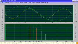
These two very different analog signals, when sampled by the ADC without any filter, will yield exactly same stream of samples:

blue line - signal A, yellow line - signal B, circles - sampled signal A, crosses - sampled signal B
Now how can the processing stage 2 distinguish between the two signals when in both cases it receives identical data to process? IMO it will claim H2 at -12dB for both cases, even though for case B) the 20kHz signal has zero harmonic distortions.
Or another case B) - combination of -18dBFs H2 and -18dBFs spurious 8kHz, yielding again identical samples as case A)

All because all the upper frequencies are "folded" to <0, fs/2> and only knowledge of which fs/2 interval was being band-passed to the ADC stage allows to specify which frequency of the many (infinite for infinite bandwidth) mirrors is the correct original one. But there is no analog band-passing prior to the ADC being mentioned as requirement for diana, if I understand correctly.
There are some great figures at https://www.eetimes.com/how-to-use-undersampling/#
That is my opinion. Where am I making a mistake?
The octave source for the modified case B is stored at Plotting undersampled signals * GitHub
Stage 1 - Data acquisition, resulting in a stream of samples
Stage 2 - Processing of the acquired stream.
The scope undersampling mentioned by Demian requires controlled data acquisition (trigering at exact part of the waveform, random sampling times to increase the effective sample rate). However, none of that is possible with a typical ADC. The exact sampling start cannot be specified and sampling times are all equal. Only several fixed sampling rates (multiples) are available. The Stage 2 receives a steady flow of equally timed samples.
Now these stages are independent - Stage 2 cannot influence the timing and values of data it receives from the data acquisition stage.
Let's assume an ADC with no low-pass filter, doing just regular sampling of the continuous (analog) signal (e.g. SAR ADC). The sample rate is 48kHz.
Case A)
The sampled analog signal is 20kHz fundamental at -6dBFs + H2 (40kHz) at -12dBFs, all zero-phase based.
Case B)
The sampled analog signal is 20kHz fundamental at -6dBFs + spurious 8kHz at -12dBFs with inverted phase at start.
These two very different analog signals, when sampled by the ADC without any filter, will yield exactly same stream of samples:
blue line - signal A, yellow line - signal B, circles - sampled signal A, crosses - sampled signal B
Now how can the processing stage 2 distinguish between the two signals when in both cases it receives identical data to process? IMO it will claim H2 at -12dB for both cases, even though for case B) the 20kHz signal has zero harmonic distortions.
Or another case B) - combination of -18dBFs H2 and -18dBFs spurious 8kHz, yielding again identical samples as case A)
All because all the upper frequencies are "folded" to <0, fs/2> and only knowledge of which fs/2 interval was being band-passed to the ADC stage allows to specify which frequency of the many (infinite for infinite bandwidth) mirrors is the correct original one. But there is no analog band-passing prior to the ADC being mentioned as requirement for diana, if I understand correctly.
There are some great figures at https://www.eetimes.com/how-to-use-undersampling/#
An externally hosted image should be here but it was not working when we last tested it.
An externally hosted image should be here but it was not working when we last tested it.
An externally hosted image should be here but it was not working when we last tested it.
An externally hosted image should be here but it was not working when we last tested it.
That is my opinion. Where am I making a mistake?
The octave source for the modified case B is stored at Plotting undersampled signals * GitHub
Last edited:
[...]
Let's assume an ADC with no low-pass filter, doing just regular sampling of the continuous (analog) signal (e.g. SAR ADC). The sample rate is 48kHz.
Case A)
The sampled analog signal is 20kHz fundamental at -6dBFs + H2 (40kHz) at -12dBFs, all zero-phase based.
Case B)
The sampled analog signal is 20kHz fundamental at -6dBFs + spurious 8kHz at -12dBFs with inverted phase at start.
These two very different analog signals, when sampled by the ADC without any filter, will yield exactly same stream of samples:
Now how can the processing stage 2 distinguish between the two signals when in both cases it receives identical data to process? IMO it will claim H2 at -12dB for both cases, even though for case B) the 20kHz signal has zero harmonic distortions.
[...]
Hi Pavel,
You are right. In this (special!) case DiAna isn't able to differentiate between a real harmonic and a spurious. The good news is, however, that it won't happen that much. It only happens when the frequency of the spurious exactly coincidences with a folded (aliased) harmonic. When I increase (or decrease) the spurious frequency by 1%, the "claimed" H2 is more than 100dB* lower. So in case of any doubt one could change the fundamental frequency a little bit and compare the results. If still the same, then DiAne isn't fooled by a spurious.
Cheers, E.
* Obtained this figure by means of simulation.
- Home
- Design & Build
- Equipment & Tools
- DiAna, a software Distortion Analyzer