Jackd is using alsa (just like pulseaudio). The most typical problem is pulseaudio has taken your USB soundcard, which prevents all other processes from access to the soundcard. You can easily tell which process is currently using your sound device (btw try to find such info in the other non-can-of-worms OSes):
It is just a few clicks in pavucontrol or PA control panel of your distribution to tell PA to avoid the soundcard.
I prefer a system which I can fully diagnose and fix, at every level of the stack, to a black box where only the manufacturer sort of knows how it works and can modify, and where the only troubleshooting technique is endless trial and error. Plus fighting problems from completely unrelated areas such as false positives by the myriad of buggy "antivirus" tools.
Code:
sudo lsof /dev/snd/*It is just a few clicks in pavucontrol or PA control panel of your distribution to tell PA to avoid the soundcard.
I prefer a system which I can fully diagnose and fix, at every level of the stack, to a black box where only the manufacturer sort of knows how it works and can modify, and where the only troubleshooting technique is endless trial and error. Plus fighting problems from completely unrelated areas such as false positives by the myriad of buggy "antivirus" tools.
Last edited:
Hi Jan,I tried to characterize the AP notch filter but it doesn't seem to work. Probably some interference from what the AP thinks it should do.
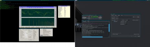
I set the AP to fixed 1kHz notch, set DiAna to 1kHz too. Edmond, the waveform I see in characterisation mode, is that the ref channel or the test channel? It shows a rather distorted wave, 20% THD, looks like strong xover.
The output of the notch on the scope looks like the usual noise with little signal detectable, which is to be expected.
Jan
A highly distorted waveform is correct. This is because we need a lot of harmonics to determine the response of the notch filter at precisely these frequencies. What you see is a sawtooth waveform superimposed on a sine. See also post 763.
Cheers, E.
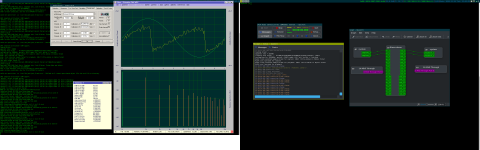
Diana works in a linux setup. Install wine, wineasio , qjackctl. And setup as 32bit windows.
I have done it in archlinux , the "Amplitude" and "Vert.Scale" is not correct but I think everything else is correct.
It feels stable, no problems with "Super user" rights etc.
I have done it in archlinux , the "Amplitude" and "Vert.Scale" is not correct but I think everything else is correct.
It feels stable, no problems with "Super user" rights etc.
Attachments
Last edited:
Hi Jan,
A highly distorted waveform is correct. This is because we need a lot of harmonics to determine the response of the notch filter at precisely these frequencies. What you see is a sawtooth waveform superimposed on a sine. See also post 763.
Cheers, E.
Yes indeed! I added this to our online in-progress user guide.
I will try this procedure again.
BTW Could you add a few words at the paragraph 'Using DiAna as an oscilloscope' , I will massage then.
Jan
100% agreed.I prefer a system which I can fully diagnose and fix, at every level of the stack, to a black box where only the manufacturer sort of knows how it works and can modify, and where the only troubleshooting technique is endless trial and error. Plus fighting problems from completely unrelated areas such as false positives by the myriad of buggy "antivirus" tools.
And thank you for your kind advice, will try that.
You did it! Great! As for incorrect amplitude and vert. scale, are you sure you have entered the correct calibration factors?Diana works in a linux setup. Install wine, wineasio , qjackctl. And setup as 32bit windows.
I have done it in archlinux , the "Amplitude" and "Vert.Scale" is not correct but I think everything else is correct.
It feels stable, no problems with "Super user" rights etc.
Cheers, E.
I never got it to work with 64 bit or 32 bit. I suspect it may have to do with bad drivers for my motherboard audio that ruin everything else.
@jan.didden it would be nice to have your "autoranger" controlled from Diana ? Is that possible?
@jan.didden it would be nice to have your "autoranger" controlled from Diana ? Is that possible?
Everything is possible but at the moment there is no external connection to set the attenuation or to report the level. It would require a USB interface and some subroutines. Also it would require substantial software changes in DiAna I would guess.
Not rocket science but too much going on at this time to work on that, unfortunately.
Jan
Auto ranging
Indeed, everything is possible. But... the more features and gadgets, the more can go wrong. Maybe in the future I will implement an option for auto ranging with the RTX, but only to correct serious fault conditions (i. e. heavy overloading of the DAC or ADC).Everything is possible [...]
Jan
Everything is possible but at the moment there is no external connection to set the attenuation or to report the level. It would require a USB interface and some subroutines. Also it would require substantial software changes in DiAna I would guess.
I do not know about the autoranger specifics, but I would like to mention the most simple and economical option for adding remote USB control/monitoring to any new or existing project - the Arduino Firmata.
Firmata is a standard protocol for controlling MCU peripherals from host software over serial port. It has simple libraries available basically for any programming language GitHub - firmata/protocol: Documentation of the Firmata protocol. . Reading/writing to pins, reading ADC values, I2C communication, etc. is just a matter of one or a few lines of code in the host software, easy to add into any existing project.
Arduino Nano with on-board USB-serial chip costs < 2USD incl. shipping (e.g. Nano Mini USB Development Board Nano V3.0 Controller Board ATmega328P CH340G USB to TTL NANO 3.0 for Arduino with USB Cable-in Integrated Circuits from Electronic Components & Supplies on AliExpress ) . Powered by the USB host, it can read/control the existing device directly, or via some inexpensive galvanic isolators (solid state relays, optocouplers). The arduino is programmed directly from the Arduino IDE, just select the Standard Firmata sketch available directly in the IDE and burn via USB to arduino, a few minutes of work even for beginners, incl. download and installation of the Arduino IDE.
The default serial port runs at 57600 bps, the protocol is binary MIDI format, making communication reasonably fast. In my interpreted octave (i.e. slow) a call to digitalWrite(pin, value) takes about 1ms.
For nice design a panel-mounted USB female short adapter cable costs next to nothing Mini USB Male to Female connector Adapter extend Cable With Panel Mount Hole es | eBay
IMO in many cases there is no need to add USB chips and program some firmware changes. Using arduino firmata and coding simple logic in the host PC directly may reach the goal much faster, cheaper and more flexibly.
Last edited:
IMO in many cases there is no need to add USB chips and program some firmware changes. Using arduino firmata and coding simple logic in the host PC directly may reach the goal much faster, cheaper and more flexibly.
So if I understand you correct some controller pins input/output on Autoranger and then into an arduino(with some code) and with the interface for/to USB.
@jan.didden are there Ext. set possibility on the new Autoranger?
I do not know about the autoranger specifics, but I would like to mention the most simple and economical option for adding remote USB control/monitoring to any new or existing project - the Arduino Firmata.
Firmata is a standard protocol for controlling MCU peripherals from host software over serial port. It has simple libraries available basically for any programming language GitHub - firmata/protocol: Documentation of the Firmata protocol. . Reading/writing to pins, reading ADC values, I2C communication, etc. is just a matter of one or a few lines of code in the host software, easy to add into any existing project.
Arduino Nano with on-board USB-serial chip costs < 2USD incl. shipping (e.g. Nano Mini USB Development Board Nano V3.0 Controller Board ATmega328P CH340G USB to TTL NANO 3.0 for Arduino with USB Cable-in Integrated Circuits from Electronic Components & Supplies on AliExpress ) . Powered by the USB host, it can read/control the existing device directly, or via some inexpensive galvanic isolators (solid state relays, optocouplers). The arduino is programmed directly from the Arduino IDE, just select the Standard Firmata sketch available directly in the IDE and burn via USB to arduino, a few minutes of work even for beginners, incl. download and installation of the Arduino IDE.
The default serial port runs at 57600 bps, the protocol is binary MIDI format, making communication reasonably fast. In my interpreted octave (i.e. slow) a call to digitalWrite(pin, value) takes about 1ms.
For nice design a panel-mounted USB female short adapter cable costs next to nothing Mini USB Male to Female connector Adapter extend Cable With Panel Mount Hole es | eBay
IMO in many cases there is no need to add USB chips and program some firmware changes. Using arduino firmata and coding simple logic in the host PC directly may reach the goal much faster, cheaper and more flexibly.
The controller I use, a PIC16F1788 has a version with build-in USB. Except no more pins available. So it's a major upgrade, and my stack of projects is tall already.
I'll give it a thought.
Jan
So if I understand you correct some controller pins input/output on Autoranger and then into an arduino(with some code) and with the interface for/to USB.
Exactly. The arduino firmware is standard firmata sketch, no coding on your side, just burn it directly from Arduino IDE.
You only code the simple control commands in your PC software. Basically the cheap arduino + USB adds GPIOs and basic hardware interfaces to your x86 PC, making it suitable for direct control like RPi with its native GPIOs.
As of the autoranger you could add a shim between the flat control cable and the analog board. That cable must carry control signals for the relays. BUT you would be interfacing at the lowest level, below the control MCU. For reading (monitoring) the status OK, no way for control as you would be bypassing the device MCU.
If the autoranger had push buttons up/down, you could interface with the buttons (write) and the relays (read) to have complete control. Still the control code would be very short, e.g. in python or whatever a project is written in.
My octave project has just started operating stepper motors, after extending a firmata library for octave with support for firmata module AccelStepper, not supported by that simple client yet. A few functions written in octave, no programming for arduino (the stock firmata arduino firmware already supports the accelstepper protocol). Firmata yields simple results fast.
The controller I use, a PIC16F1788 has a version with build-in USB. Except no more pins available. So it's a major upgrade, and my stack of projects is tall already.
Yeah, adding a custom external control is a major project. Plus you need all the host-side code too. I am talking about using a standard protocol, with standard hardware. If your project has manually-operated controls and the status can be read somehow, it is trivial to interface with an added arduino to operate externally.
Please I am not saying you should change your project, I am just showing a very simple and inexpensive option I have not seen to be used by people here.
E.g. had RTX used USB-serial firmata instead of their HID protocol, adding support would have been WAY easier, for any analyzer (diana in C++, mataa in octave, REW in java etc.).
Exactly. The arduino firmware is standard firmata sketch, no coding on your side, just burn it directly from Arduino IDE.
You only code the simple control commands in your PC software. Basically the cheap arduino + USB adds GPIOs and basic hardware interfaces to your x86 PC, making it suitable for direct control like RPi with its native GPIOs.
As of the autoranger you could add a shim between the flat control cable and the analog board. That cable must carry control signals for the relays. BUT you would be interfacing at the lowest level, below the control MCU. For reading (monitoring) the status OK, no way for control as you would be bypassing the device MCU.
If the autoranger had push buttons up/down, you could interface with the buttons (write) and the relays (read) to have complete control. Still the control code would be very short, e.g. in python or whatever a project is written in.
My octave project has just started operating stepper motors, after extending a firmata library for octave with support for firmata module AccelStepper, not supported by that simple client yet. A few functions written in octave, no programming for arduino (the stock firmata arduino firmware already supports the accelstepper protocol). Firmata yields simple results fast.
I understand that. But would you also not want to know the actual signal level coming in?
Jan
I understand that. But would you also not want to know the actual signal level coming in?
Jan
A full-featured control support integrated with the device is always better, of course.
Arduino has 12bit ADC, perhaps it could interface at some point - the same your MCU taps the input signal.
On the other hand - the analyzer already knows dbFS value. If it also knew status of attenuator relays -> easy calculation.
- Home
- Design & Build
- Equipment & Tools
- DiAna, a software Distortion Analyzer