As I should be receiving that same kit from Tubehunter too, and there seems to be some problems with the parts quality, I started researching on the output 5W .33 ohms emitter resistors, and see what might be the options.
What I am looking for is high quality options, and I found a type at Mouser that looks interesting:
MOSX5LR33J KOA Speer Metal Oxide Resistors
The type is right (metal oxide), the price too ($1), but you need to buy 500 minimum.
Does anybody sell this resistors in small quantities?
What I am looking for is high quality options, and I found a type at Mouser that looks interesting:
MOSX5LR33J KOA Speer Metal Oxide Resistors
The type is right (metal oxide), the price too ($1), but you need to buy 500 minimum.
Does anybody sell this resistors in small quantities?
Last edited:
They are 0.22ohm resistors...0.33 is ok too..you will not have problem.if you like buyng from ebay: http://cgi.ebay.es/30x-0-22-ohm-0R2...564?pt=LH_DefaultDomain_0&hash=item414aa2e874
Bye
Bye
In what do those eBay resistors differ from those on the kit? They look the same on the photo.
It's OK to go down in value up to a point with those resistors, and 0.22 ohms should be fine indeed.
It's OK to go down in value up to a point with those resistors, and 0.22 ohms should be fine indeed.
Thanks dinamic1,
I bought some power transistors from EBay in the past and these seemed to be OK. They are working now in my Mimesis amps. Maybe I was lucky but on the other hand the PS is below 50V per rail so who knows. I wanted to buy directly from OnSemi but their shipping costs to Australia are far too high. I'll get my new mjl3281/1302 devices from BDEnt.
As John suggested I'd try to increase bias to 75-100mA. I run my lateral mosfet amp at 150mA and Mimesis at 100mA. Under normal listenning conditions heatsinks are not hot.
In my mosfet amp the main heating problem is with VAS which currently runs at 32mA.
cheers,
Edit: 10 mv is the manufacter recomendation..you can trim from 10mv to 30mv...be careful here with the dimensions of your heatsink.
10mv across 0.22 ohm is about 45mA. In simulations higher bias showed better results (lower crossover distortions, thd, intermodulation) but of course the OS runs hotter. It was sensitive to the quality of PS. Regulated PS for the input-vas was the best option.
Did you try this or input-vas PS is separated from the output PS by 33ohm only?
The most important thing is that it sounds well.
cheers,
Did you try this or input-vas PS is separated from the output PS by 33ohm only?
The most important thing is that it sounds well.
cheers,
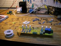
Hello Janusz..no, my PS is a linear one..l think good quality (see pics) best results in this amp perhaps with 20mv (conservative)..of course most important thing is how it sounds..and l must say it sounds VERY VERY VERY GOOD.
Cheers..
Cheers..
no, my PS is a linear one..l think good quality (see pics) best results in this amp perhaps with 20mv (conservative)..of course most important thing is how it sounds..and l must say it sounds VERY VERY VERY GOOD.
I think Janusz was asking if you were using any regulator for the input & VAS stages, not if your supply was a switching type.
On my Diamond I do intend to use regulators on the low-current stages.
But first I have to devise a way to test the coming transistors with high voltages and under load. Any suggestions?
l understand what janusz means..some power amps needs regulated power supply on first stages..l think this one not...the only one metod to "test" devices is to put on place and praise the lord to have a bit of luck.. 🙂
dinamic,
One more question. In your Diamond version - how are R22 and R23 resistors connected? Do these link emiters of Q17 and Q18 to the nfb line linking the output via the gain setting resistors with the inner side of LTP? or these resistors provide only a floating connection to Q17 and Q18 drivers?
On my board they go to the nfb line but I'd prefer them being floated.
cheers,
l understand what janusz means..some power amps needs regulated power supply on first stages..l think this one not..
Allow me to disagree on this. All amps improve with regulated supplies, which should be used at least on the first stages.
Some may find this improvement to be important, some others may not. But it's there.
There was an article on The Audio Amateur, a long time ago, where a Borbely 60w amp was modified, adding a 317/337 regulator on the low current stages, and figures were provided for improvement on many areas.
So it's not a subjective thing. You should try it.
I thought this amp was supposed to be a clone of the Accuphase E-305V seen here:Accuphase/kensonic Accuphase E-305
I am in the process of building one.Almost have one board complete.
The schematic was available only by email enclosure so the schematic posted at the start of this thread is much better quality.Thank you for posting that.
Looks like I am missing only two parts.R8 and R15 which I believe should be rated at 470 ohms each.
Any followup posts on these builds are welcome.Pics are good too.
Accuphase E305V clone pics
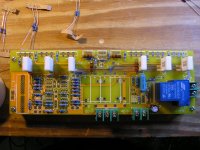
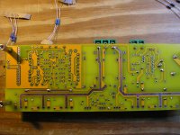
Some pics of the Diamond Differential design Accuphase E305V clone build in progress.
Some pics of the Diamond Differential design Accuphase E305V clone build in progress.
Attachments
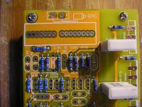
In picture #3 at top center you see two nodes and the notation RAC.
What does RAC stand for? The symbol looks like a battery.
What does RAC stand for? The symbol looks like a battery.
Now looking at the schematic shown in the original post I can't find R8 or R15 but the components included only four 470 ohm resistors so that would be two per board and all others seem to be accounted for.Guess I'm going with the 470's in there.
Another question.What is the value of capacitor 104 which can be seen in the second pic above towards the left side at the top of the first bank of resistors? and again in the bank of resistors to the right.
Now I have just one capacitor rated at 10uF 50vdc axial per side with no hole to solder it in to.Any one know about this?
- Status
- Not open for further replies.
- Home
- Amplifiers
- Solid State
- DIAMOND DIFFERENTIAL INPUT POWER AMPLIFIER EBay kit