Welcome to the club!!My first play with LT Spice
I see that Sansui ckt used in many Sansui hi-end designs, used for phono amps on to PAmps!!
Welcome to the club!!
I see that Sansui ckt used in many Sansui hi-end designs, used for phono amps on to PAmps!!
Circuit post by Wahab in post #54 ?
My diamond circuit use dual differential bjt input stage compare to Sansui single fet input stage.
To bad he did not post .asc file, I guess I will have to draw it up myself, if I want to simulate it and compare.Circuit post by Wahab in post #54 ?
Yes I do realize the difference in topology.
Your diamond ckt, looks similar to the Marshall Leach ckt? Borbely used the same symetrical front end as well?
To bad he did not post .asc file, I guess I will have to draw it up myself, if I want to simulate it and compare.
Yes I do realize the difference in topology.
Your diamond ckt, looks similar to the Marshall Leach ckt? Borbely used the same symetrical front end as well?
The input stage is supplied with + /-15V stabilized by zeners, which also determines the constant current of input differential pairs and diamond differential to which it is connected. There is no cascade connection and there is no direct connection to the VAS like in Marshall Leach ckt and other ckt with simple symmetric front and.
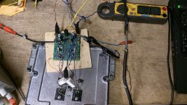
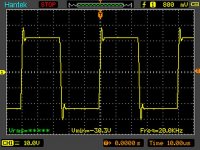
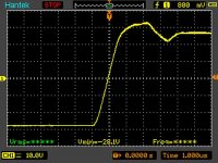
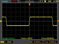
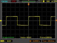
Yes that meas on my desk is hd amp (bit different schematic).
It is working and playing right now. There is some work left to do but most important is that is working.
I didnt putted zeners at front end, I putted 2x2n5xx1 CCS instead.
With big amplitude I am gettin overshoot and bias is under compensated (I have to check this case too).
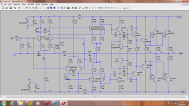
1st stage - 4mA
2nd stage - 5mA
VAS - 20mA
Driver - 13mA
There is some brumming issue but prapobly due my shitty board.
Amp is playing nice anyway - this is good promissing sign.
It is working and playing right now. There is some work left to do but most important is that is working.
I didnt putted zeners at front end, I putted 2x2n5xx1 CCS instead.
With big amplitude I am gettin overshoot and bias is under compensated (I have to check this case too).
1st stage - 4mA
2nd stage - 5mA
VAS - 20mA
Driver - 13mA
There is some brumming issue but prapobly due my shitty board.
Amp is playing nice anyway - this is good promissing sign.
Attachments

Yes that meas on my desk is hd amp (bit different schematic).
It is working and playing right now. There is some work left to do but most important is that is working.
I didnt putted zeners at front end, I putted 2x2n5xx1 CCS instead.
With big amplitude I am gettin overshoot and bias is under compensated (I have to check this case too).
1st stage - 4mA
2nd stage - 5mA
VAS - 20mA
Driver - 13mA
There is some brumming issue but prapobly due my shitty board.
Amp is playing nice anyway - this is good promissing sign.
Nice work, zeners must be used, DD need stabilized voltage on input for constant current, this topology promissing. DC offset circuit must be add as next circuit upgrade.
Regards
I do not have 15v zeners, can i use 24v ones and change two resistors for correct bias? Another think is if i can use 10k pot instead of two 5.6k resistors for first stage ? Differential amp on legs 1 and 3 and zener psu on leg 2? Or better do standart offset adjustment
Last edited:
I do not have 15v zeners, can i use 24v ones and change two resistors for correct bias? Another think is if i can use 10k pot instead of two 5.6k resistors for first stage ? Differential amp on legs 1 and 3 and zener psu on leg 2? Or better do standart offset adjustment
Use zeners with voltage under 15V (8v2, 9v1...) or separate +/-15V psu (LM7815/7915...) and remove 1k/2W resistors.
For dc offset you can use any circuit or dc servo with op amp.
Last edited:
Hi Mile,
which one is almost ready to be build?
I want to try make a PCB layout for it.
post #43 or #60 ?
Or the latter one?
with servo like the SR-version 🙂
Regards
which one is almost ready to be build?
I want to try make a PCB layout for it.
post #43 or #60 ?
Or the latter one?
with servo like the SR-version 🙂
Regards
Last edited:
Hi Mile,
which one is almost ready to be build?
I want to try make a PCB layout for it.
post #43 or #60 ?
Or the latter one?
with servo like the SR-version 🙂
Regards
This simple circuit can be use for dc offset...
Attachments
Keep on going this project.
My comment is just about the naming.
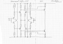
From my perspective this thread is showing only one schematic with a diamond topology and this was the Non Differential Elektor Diamond.
Attached a principal sketch of an input configuration which I would link to the title of thread.
My comment is just about the naming.
From my perspective this thread is showing only one schematic with a diamond topology and this was the Non Differential Elektor Diamond.
Attached a principal sketch of an input configuration which I would link to the title of thread.
Attachments
Keep on going this project.
My comment is just about the naming.
From my perspective this thread is showing only one schematic with a diamond topology and this was the Non Differential Elektor Diamond.
Attached a principal sketch of an input configuration which I would link to the title of thread.
Is this diamond differential with diamond buffers input stage?
its been very clearly stated by several other knowledgeable members that this diamond differential amp design is a Sansui speciality
and from what I understand also quite old, and designed before the diamond buffer
(I have no idea where the diamond buffer got its name from, or why)
would this put the name game to rest ?
and from what I understand also quite old, and designed before the diamond buffer
(I have no idea where the diamond buffer got its name from, or why)
would this put the name game to rest ?
Exactly. So far the naming 'diamond' typically is used for this PNP-NPN/NPN-PNP combination, which often used for buffers.
Some amps use this diamond approach also an input stage.
By combining two diamonds like in my sketch you can easily settle a very linear differential input stage with high input impedance and need nothing but cheap small signal BJTs.
Edit:
Above answer links to posting #73
@Tinitus
...cannot comment on the history of Sansui namings.
Possible that they used the name earlier.
Feel free to go for a research when the diamond buffer was born and when Sansui named its circuit diamond.
Last edited:
Attached a principal sketch of an input configuration which I would link to the title of thread.
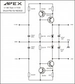
Congrats...you've just (almost) drew Krell FPBxxx amplifier input stage

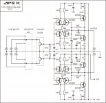
Sansui s diamond circuit is a fet single differential that drive
a symmetrical differential , see below.
well, I suppose it's ok to be confused now 😀
but is it possible to say what makes it such, or why its called a diamond amp 😕
do I need to say you can click on the blue arrow in the quote to show original post
@Tinitus
...cannot comment on the history of Sansui namings.
Possible that they used the name earlier.
Feel free to go for a research when the diamond buffer was born and when Sansui named its circuit diamond.
I hoped someone would know the origin of the Diamond name, or when used first
well, I suppose it's ok to be confused now 😀
Yes you can😀...What is well known is Sansui DD (Diamond Drive) circuit (emitter connected complementary differential in this thread)...what's in front of it...who cares?😀
well, we do have a thread with Sansui's original Diamond Differential Amp
http://www.diyaudio.com/forums/soli...nt-mirror-loads-self-biased-vas-cascodes.html
http://www.diyaudio.com/forums/soli...nt-mirror-loads-self-biased-vas-cascodes.html
- Home
- Amplifiers
- Solid State
- Diamond Differential Amplifier