Well selected components can have quite a benefit in the right locations and can take an amp from quite good to exceptional. Choose poorly and it goes backwards quickly. 🙁
But on the other hand my hearing isn't the same like yours.As I say this is the sound for me you can say I don't like it.
I also think that different brands of caps can make or brake down the sound that you like to hear.That's the fine tuning over time but you have to start somewhere and you have to rely on someone elses nohow.
I also think that different brands of caps can make or brake down the sound that you like to hear.That's the fine tuning over time but you have to start somewhere and you have to rely on someone elses nohow.
Well... i can see that Nordic have really learned a lot
And now a days already discussing with the designer.... having personal experiences those last monthes that goes against 47 years i have doing those things.
It seems to be a huge progress...only a gênius is able to that.
Congratulations Nordic.... a couple of monthes or year doing audio and now a days you have better knowledge than the old folks!
But i suggest you to follow the designer instructions about condensers sizes and that stuff, as the responsability related the sonic result will be with the designer.
When we install 4700uf into a circuit board, the result is not only because the 4700uf..... other factors contribute, and not only the increase of capacitance.... say, some increase in sonics can be consequence of bad supply filtering, not the need of big condensers into the board....there are other factors too..but will not explain, as you know more than i know, so i will let you to explain.
regards,
Carlos
As Carlos said, chooseing the biggest part you can get is not by definition the route to audio bliss... I did my best to also specify the brand and type of cap I used on my favourite HRII so far.
Also recommend you start at the miminum values indicated on the PCB (470uF) to first hear the intended circuit, and then start experimenting.
I am bussy putting together a unit now with 1000uf for the front and 4700uf for the output section.
Next one will have 470uf (as suggested in Post 615) and 2200uf, this will give 3 setups to do AB tests with.
Of coarse experience always wins in the long run, and what suited this amp may be less of a one size fits all solution than folowing conventional advice.... I.e. always listen to the established advice first... then try your own thing.
Some things that will be worth it, is Mica caps For C21 (if you have a scope you can reduce the value of this cap while checking for stability.)
Also Mica caps for the 10pf and 220pf units.
Attachments
A to B testing is the best tool we have to find solutions
But fair A to b testing is the BLIND A to B testing.
Because we use to fool ourselves.... if we replace a small condenser by a huge one, wishing huge sound, big bass and those things. we are already half way to perceive it as better.
This is very normal and used by many bad people..... as they know the power of Self suggestion.
We cannot know the ones is playing....make one channel with small condenser and other channel with big ones... say...big capacitances...and them call someone to switch from one to the other with the same audio source and into the same speaker.
Remember that..not knowing the one is playing, you will evaluate better.
Also check you supply condensers if you decided to the one has bigger condensers, it is possible that the units into the board are behaving in a complementary way..filling the needed capacitance you do not have into your supply...weak transformer are very helped with huge capacitances.
Then, decided the one you prefer, let us know and keep the best option into your boards.
be happy,
regards,
Carlos
I could not read people posting their final thougths about the amplifier
I had only few people that said have assembled and no one told had problems.
This creates into my mind some suspections that some folks had problems
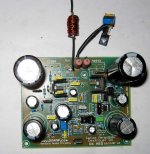
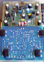
I was watching the board once again, and cleaning once more, and i have found that copper lines are really very close one each other...so...the danger to have short is very big...because of that, i strongly suggest you to clean the board after finish solder, and inspect each connection using lenses to observe details.
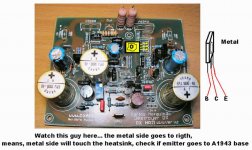
Also, you can be confused by the driver transistor position.... check if you have installed the one with the emitter soldered into the copper line that will go to the power transistor base...check both drivers for position into the board.
There's a link also into the board that cannot be missed.
In my image you see the squared things down the boards..they are 0.1uF capacitors, also used as insulators to glue the board directly over the heatsink surface.
Measure your boards when finish....in advance to put power on them, and of course, do not forget the protective series resistances.... check supply for polarity twice!
Measure with a 200K range...you will see resistances increasing because of the electrolitic condensers charging.... go watching to see them go above 20K.... do not need to wait the final reading.
Check from positive to ground, from negative to ground, from positive to negative and invert your probe points to repeat the precious steps.
No one will show you small resistances unless you have installed protective diodes into the rails.
Small resistance means shorts into the copper lines or parts assembled wrong way.
I wish you luck, and also i would be happy to see some images posted...your construction posted.
regards,
Carlos
I had only few people that said have assembled and no one told had problems.
This creates into my mind some suspections that some folks had problems
I was watching the board once again, and cleaning once more, and i have found that copper lines are really very close one each other...so...the danger to have short is very big...because of that, i strongly suggest you to clean the board after finish solder, and inspect each connection using lenses to observe details.
Also, you can be confused by the driver transistor position.... check if you have installed the one with the emitter soldered into the copper line that will go to the power transistor base...check both drivers for position into the board.
There's a link also into the board that cannot be missed.
In my image you see the squared things down the boards..they are 0.1uF capacitors, also used as insulators to glue the board directly over the heatsink surface.
Measure your boards when finish....in advance to put power on them, and of course, do not forget the protective series resistances.... check supply for polarity twice!
Measure with a 200K range...you will see resistances increasing because of the electrolitic condensers charging.... go watching to see them go above 20K.... do not need to wait the final reading.
Check from positive to ground, from negative to ground, from positive to negative and invert your probe points to repeat the precious steps.
No one will show you small resistances unless you have installed protective diodes into the rails.
Small resistance means shorts into the copper lines or parts assembled wrong way.
I wish you luck, and also i would be happy to see some images posted...your construction posted.
regards,
Carlos
Attachments
Honestly, i did not get very long yet. I've been involved in building two 160M transmitters with tx-automatic, and a handfull of recievers to track them down ( fox hunting ).
This takes all my time because it's a very looong time since i messed with similar things, so i have to learn all over again, and learning curve becomes steeper as years pass by 😀
But... I haven't given up, will eventually succeed. The only thing i need to find is C9 and C10, with a small enough footprint to fit the pcb.
I can give You all a simple picture, though it doesn't tell much
Attachments
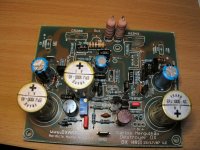
Thank you, the board image Ebbe.
Interesting those Frako condensers...they were famous into Brazil, we used to call them Fraco (means weak in my language)..... they were excelent, just the brand Frako has this direct meaning translation to my language.... Frako, or Fraco means weak in Portuguese.
Thank you very much, by your kindness to produce picture and post it here.
Also very interesting you have radio activity into 160 meters....the BD139, also TIP41 works fine into those frequencies, as drivers and output .... a nice QRP (low powered transmitter) can be made with them.
Send me the schematic Ebbe
panzertoo@yahoo.com
regards,
Carlos
Attachments
ATTENTION, atenção, atencion, achtung, atento!
ATTENTION!.... easier bias adjustment to HRII Post #4761
I found it boring, and 2 guys already told the amplifier goes underbiased when first pré set adjustment is made.
So i have modified the unit to make it behave more kindly to adjustment.
There's one resistance between driver's emitters, it is marked as 180 ohms.... try to reduce it to 150 ohms
The phase advance resistances, 470 ohms in paralell with 100N... reduce this resistance to 100 ohms...the effect will be reduced but the drivers will work more happy into a better operation point.
Do not forget to include heatsinks into the drivers, because without them you will have thermal drift....your current will increase...and increase...and increase and Booooom!
The input, as Nordic said, 8 to 10uF work better.... this is fact!
The gain resistances, into the feedback, the ones marked as 390 ohms... good idea to reduce them to 220 ohms each one of them.
The treble booster is not needed.... i suggest you to keept it off.
Do not forget to connect the zobel into the ground...it is a wire jumper that runs under the board....i have tried and result fine with 68pF into the Miller compensation....but 82pf will be good and 100pf will be excelent....not really needed to use 150pf.... reduce it as audio overall quality will increase a lot.
I felt not really needed condenser into the VBE multiplier, from coletor to emitter...but, if you like it...install 2uF there..positive to colector.
I have tested the unit into 2 ohms speakers...worked great!,..... but a little bit dangerous if your supply can maintain the voltage into a steady state, without reduction during peaks of consumption, them you will exceed the maximum power ratio into the output transistors...but really pumped a great sound...more than excelent!
I decide to adjust it to low bias...was not bigger than 40 miliamps
Voltage tested was rock stable (electronic stabilizer) into 35 volts and after the rail regulators the voltage is 32.5V
I have measured 2 mV over the 0.22ohms emitter resistances we have in the output stage
515 milivolts measured, as VBE into the output.
575 milivolts measured, as VBE into the drivers
550 milivolts measured, as VBE into the differential transistors
600 milivolts measured, as VBE into the first VAS transistor (546)
550 milivolts measured, as VBE into the second VAS (BD139)
Bias trimpot adjusted to 798 ohmns
Following this procedure, i am sure you will be more happy during the adjustments.
regards,
Carlos
__________________
http://users.tpg.com.au/users/gerskine/dxamp/
Hi Ebbe they realy don't need to be 10000uF... (it won't hurt either). I can suggest the caps I used from RS components as you are in Europe. They were slightly expensive but not rudely so.
Also you could get for any other cap in that footprint and at least 50V, even down to 3300uF.
Also you could get for any other cap in that footprint and at least 50V, even down to 3300uF.
Nordic said:Hi Ebbe they realy don't need to be 10000uF... (it won't hurt either). I can suggest the caps I used from RS components as you are in Europe. They were slightly expensive but not rudely so.
Also you could get for any other cap in that footprint and at least 50V, even down to 3300uF.
Hi Nordic.
I did manage to find some 4700uF 50v at my usual "pusher", but it is a very strange size, 25mm high, and 35mm wide, so that was not the bargain i hoped for. I know about RS, but they are not very willing when private people like me wants to buy from them.
Nevermind, i will eventually find them, am too busy ATM anyway, and frankly, i'm also over my budget for the next few months 😀
Greetings to all builders, constructers and distributors here. 🙂
RS sells to the public, I buy from them all the time... in private capacity...
the caps I used was stock no 3396887 and is sold in multiples of 1 🙂
Carlos, is of the opinion that even 470uF is enough there... so don't get held back by it.... 🙂
Please go check the regular thread for suggested improvements.
the caps I used was stock no 3396887 and is sold in multiples of 1 🙂
Carlos, is of the opinion that even 470uF is enough there... so don't get held back by it.... 🙂
Please go check the regular thread for suggested improvements.
Oh, i'm following the other thread too, and i allready found out that i have plenty 1000uF, so they will be the ones to try first 🙂
Thanks a lot for Your interest Nordic.
Best regards
Ebbe
Thanks a lot for Your interest Nordic.
Best regards
Ebbe
Aahhh, Nana brother?
Which is this?
The treble booster is not needed.... i suggest you to keep it off.
Which is this?
Re: Aahhh, Nana brother?
Hi Ed.
That would be the 15nF capacitor sitting near the middle of the bord. right next to the three pin jumper. It's marked as "copt". Placed there to "lift" the treble a little bit.
Best regards
Ebbe
Ed LaFontaine said:
Which is this?
Hi Ed.
That would be the 15nF capacitor sitting near the middle of the bord. right next to the three pin jumper. It's marked as "copt". Placed there to "lift" the treble a little bit.
Best regards
Ebbe
treble boost is off when jumper is installed between pin 2 and 3 on the header pins next to it... To have it on, move jumper to pin 1 and 2
I have installed to compensate my speaker losses.
Well.... those speaker are not problem anymore.
I am using others, more traditional, more standard, better reference.... an average quality speaker.
The treble booster could saturate the amplifier very soon if you have music with big quantity of treble into the recording...so...can be also a problem, have to be used with some care...in the reality, not to burn the amplifier's image...better not to use it....because someone can be tollerant to treble distortions (harshings) and not to perceive...and go playing "burning" the good image of HRII.
People may tell you..while you will be playing musical programs having very high levels of high frequencies...trebles:
- "Very loudish you amplifierharsh, soundish interestingsh...congratulationsh.... very powerfullharsh!"
Keep jumper into 2-3 position....the position that short pin number 2 with pin number 3.... this way the treble boost will be off.
Carlos
HRII have received some small modifications, only resistances and the increase
of the input capacitor that gone to 10uF.
Board still the same..no modifications.
Here a temporary schematic, a forum friend TAJ (Todd Johnson) will prepare the schematic soon....he is very busy those days..so..we will have to wait a week maybe.
But here is something...not good quality, as i could not make it good enougth.
I will put it into Orkut and will give you the adress to go there...to copy the 140K pdf i have.
Excelent 100K pdf, or less than that, will be prepared, near future, by Todd.
regards,
Carlos
Attachments
- Status
- Not open for further replies.
- Home
- Group Buys
- Destroyer x Amplifier DX HDII version.