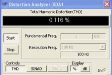
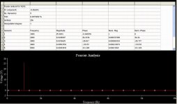
By the first time i felt curious to see the Dx Standard into fourier and
THD distortion analisis too.
Because the new one.... i want to know what is the difference in numbers to listen and understand what this means.... and if this means something to our ears...... in my experience, low numbers does not means audio quality...not always.
regards,
Carlos
THD distortion analisis too.
Because the new one.... i want to know what is the difference in numbers to listen and understand what this means.... and if this means something to our ears...... in my experience, low numbers does not means audio quality...not always.
regards,
Carlos
Attachments
Carlos,
Congratulations on your long thread on Dx amps, you have done a service to the DIY community with your lovely design.
I hope your health is OK...........
Hugh
Congratulations on your long thread on Dx amps, you have done a service to the DIY community with your lovely design.
I hope your health is OK...........
Hugh
Well dear Hugh... as you know you are a friend inside my heart
If my heart was an appartment building you would have 2 stages for you and family without paying a cent for that.... this means you live in my heart as my "ultimate audio expert", as an example to be followed not only as a technician but also as a decent man, a good father and good friend.
Thank you.... you are the one between the responsables by my evolution, not only you but also some forum friends and the forum itself.
regards,
Carlos
That "high tecnology" is only because i am using an ultimate operational amplifier
working as differential and VAS..... producing that 10 volts into the output followed by the traditional VBE multiplier and the emitter follower output (alike the Dx Standard... alike some old Aksa too).
The idea is to compare what is technically better into measurements versus something tune by ears... i use to check my beliefs... there are always a chance that i may be wrong, and this means evolution when i can change my mind.... sadly this is not happening constantly.... very rare to happens... because too many examples i had built.
A pitty that....but i have some hopes..... let's see if this nice high technology input will produce some interesting result.
As you could see, by the measurements published, seems the Dx Standard is not that bad (first time i have those informations... had not that curiosity before).... and now with a nice Burr and Brown, 0.000008% THD chip, may produce interesting results... i hope... despite i doubt a lot!
Thank you Albin..... many thanks.
This is something i think is positive in my mind and behavior...even not believing i use to give to myself the chance to see other ideas working... i do not shut the door to new ideas...i use to check them.
I have simulated the Ostripper frugalamp.... even thinking the non use of bootstrapp is not a good thing for sound... and maybe i will build it one day to be sure... i think is not scientific...i would like to substitute the "I think" by "I know"
regards,
Carlos
.......................................................................................................
Circulation is better...but only 10 percent better i think... i cannot be sitted for long time...i have to avoid that... doing this way i am keeping the return blood not acumulated down the legs near the foot.
By DX - I have simulated the Ostripper frugalamp.... even thinking the non use of bootstrapp is not a good thing for sound
Don't give up on bootstraps, they can be VERY good. I simulated
your DX standard.. got same .1% ..BUT you change slow TIP 41/2
to better 2sc japanese devices you get .03/4%.
Put a current source instead of a zener for input and you have
a AKSA amp (which sounds very good). My kids have
the little bootstrap (below) which still runs after a year.
That frugal 2T you simmed is not like the doug self amp or
a bootstrap (no VAS current source or bootstrap source)
and has a different sound than than either. the 2 sides of
the input (LPT) are in perfect balance and waves are
same from input to output BEFORE feedback . so you need
just a small amount of NFB to "fix" it ,resulting in crazy
.000368% dist. even at 20khz.
BUT , in the end , when you have them built ...side by side,
the only difference you will hear is just a little clearer highs
and better sound stage (like symasym)and only with very good speakers.
OS
Attachments
Yes Ostry... that's what was within my imagination
differences are not huge...but sometimes we can perceive them.
In the future i gonna try...now a days producing new amplifier and completing the basic audio amplifier design teaching to 8 boys into my Orkut...i gonna be more free to try near future.
regards,
Carlos
differences are not huge...but sometimes we can perceive them.
In the future i gonna try...now a days producing new amplifier and completing the basic audio amplifier design teaching to 8 boys into my Orkut...i gonna be more free to try near future.
regards,
Carlos
Boys, my chip input power amplifier is already buried deep into the grave
I found the price into local shops too much high for operational amplifier... the TL071/081 for instance..costing almost 4 US dollares..... this chip will substitute the diferential amplifier and the voltage amplifier only, and will use an extra zener diode...so... this increases the cost...no sense..not a good idea.
I can use others, but worse ones alike 4558...not a good idea.
Will not continue with that chip input idea.... will try to reduce distortion into the Standard...will manage to do that, and to try other ideas to the circuit and also to try to recalculate it to full class A, just to see the results into the simulator.... beeing good into the simulator then i will assemble to listen.
The idea is to provide my Orkut group of friends something cheap and better...this way may be better but will not be cheap.
regards,
Carlos
Well, they have asked me to use the old 4558
Well... it is not a very good chip...but cost is lower than a US Dollar here (80 cents).
This was not tested...simulated only..... 0.001% total harmonic distortion (THD) and 10 watts RMS.... the good idea is to use the 35 volts supply they have.
Just simple... a test only guys.
If you decide to build it...do it under your own risk.
Nothing is guaranteed...i have not assembled and i have doubts that small distortion can result in something special in sonics.
Of course you can install the best op amp you may find..those ones that can accept 22 volts supply.... also high speed transistors, better units...of course...it is up to you.
regards,
Carlos
Attachments
AKSA said:Carlos,
Congratulations on your long thread on Dx amps, you have done a service to the DIY community with your lovely design.
I hope your health is OK...........
Hugh
Hello Hugh and Carlos
Friday last week it was 3 years that you start the Dx amps thread Carlos.
So it was the Dx amp birthday.
Happy birthday Dx amp


Hope you will get better Carlos
Bye
Gaetan
There is no point in the 35V supplies, as the opamp wont be able to make the outputs swing much higher than about 12V.
The usual way to solve this is to give the output stage gain, with a CFP pair.
It's a good simple circuit though, used often for headphones, usually with 1N4148 diodes instead of the 30 ohm resistors
The usual way to solve this is to give the output stage gain, with a CFP pair.
It's a good simple circuit though, used often for headphones, usually with 1N4148 diodes instead of the 30 ohm resistors
Thank you Gaetan....many thanks.
The idea Jaycee, was to make it very simple with low parts count, as an exercise to Orkut friends that finally have learned how to design...just an exercise...a homework for them.
The idea is not to achieve the biggest possible power.... the chip output voltage is fine and can be even smaller than that.... also to show them that we do not need all that power.
I will not tweak the schematic.... it has a purpose...i have just published to satisfy fellows curiosity...it is not there to further developments.
Distortion is 0.001% into maximum unclipped power.... this was the main target...to be super simple and super cheap and hyper fast to assemble too.
I give up to make it a Dx Amplifier, some better idea..because i have discovered (really the first time i have measured into the simulator) the Dx Amplifier is already excelent into measurements too...the distortion is bellow human perception...i just cannot perceive bellow 0.2%...so... everything smaller than that, seems to me overkill and non sense to my own ears...i do not need that...as i cannot perceive the advantage....not really needed to waste my time with that search for smaller numbers, or higher numbers for power and efficiency.
Also, was made to show my Orkut friends, that distortion numbers does not means, always , good performance in sonic reproduction.
The study related WHAT kind of distortion may be the next step... the one bother us more or less...and i will produce schematic as example to Orkut folks to build...so... they will not need to believe me, they will have only to believe into their own ears... to accept their own perception and producing comparisons to produce conclusions.
I will not develop this schematic...also will not use it as a new Dx amplifier.... will serve those simple purposes only.
regards,
Carlos
If you want the Multisim 10 files about the Dx Amplifier simulation... the optimized
version were the total harmonic distortion is 0.025% into full power (unclipped = 50 watts RMS in 8 ohms), frequency is 1 Kilohertz.
Normal version is around 0.1% into this same measurement setup.
Some capacitors, resistances and small adjustments were made.
I do not think this may represent some audible difference, as we cannot perceive bellow 0.2% (i cannot)....so.... this is only academic and may be interesting to the ones believe in such kind of testings and numbers.
Just write to me and i will send you the Multisim 10 files.... so you just drag and drop into you multisim and click into the instruments to see what happens.
New optimized amplifier, now has 3 db losses of power into 10 hertz....and goes to 200 kilohertz without distort the sinusoidal wave entering.
The most interesting is .... when you install emitter resistances into the power transistors, the distortion increases a lot...this is interesting, as i have perceive better audio quality without those resistances and now the simulator confirms those resistances are annoying, and also the output inductor is a problem too.
panzertoo@yahoo.com
regards,
Carlos
Attachments
Build the nice Dx Amplifier, a very good amplifier
Make uncle Charlie happy!
This amplifier was hardly tested...deeply tested and built around the world by more than 300 happy folks.
No one has complained!
No one failed to build!
A very triple guaranteed schematic.
Made in our forum...with the aid of good guys
Inspired into Sony model 33 and Aksa55 (without secrets)
And reliable, a safe decision to build something will work fine.
Made as a cooperation to forum folks, without second or third intentions (to sell them is one bad intention)... was offered for free...no one, till this day, have paid for it...my payment is your happyness and your thanks... a very decent amplifier.
It is not wrong to sell things...this is the oil that lubricates the economy, the whole machine....but ... for sure you can trust in someone that say it is good when it is for free...others may say it is good thinking into the money they will earn...this is the difference only Dx Amplifier has!
heheheheheh!
Be happy too!
Build a very nice UNDISTORTED amplifier.
regards,
Carlos
Attachments

Here you have the schematic
And here you have boards and other details:
http://users.tpg.com.au/users/gerskine/dxamp/
Carlos
And here you have boards and other details:
http://users.tpg.com.au/users/gerskine/dxamp/
Carlos
Attachments
I am very proud it is distorting into so small ammount
This is a surprise to me...i was thinking it was distorting 0.5%.... good that!
Was measured full power....and people do not listen full power all time long...so...it is distorting half of nothing!
regards,
Carlos
This is a surprise to me...i was thinking it was distorting 0.5%.... good that!
Was measured full power....and people do not listen full power all time long...so...it is distorting half of nothing!
regards,
Carlos
Attachments

- Status
- Not open for further replies.
- Home
- Amplifiers
- Solid State
- Destroyer x Amplifier...Dx amp...my amplifier