No Graham.. I had not removes those ones.
I have measured that my supply loss is 3.5 volt when hard driven with Hi frequencies continuous square wave tone... also low frequencies do the same result...or almost the same.
When in iddle...supplies goes to 37 Volts.....normal listening reduce its voltage to 35 volts.
The amplifier was calculated to provide nice voltages...low VBE voltages under 35 volts...and those rail resistor are there to reduce rail voltage to a better stabilized rail voltage into the differential...lower variation of voltage in positive and in the negative rail as i have a condenser there.
So...it is there because of that.... in my imagination, the removal will not result any good for the amplifier sonics...maybe a sligtly bigger power that will not be nice compared with the voltage variations there.
Well....related that i am a little fanatic... i will not feel good removing them.... this removal will be interesting to substitute the simple supply with a double voltage supply... a sligtly bigger voltage for the input..to provide stabilized voltage and to increase a little better the swing of voltage in the output
But, of course, people is free to have a try to remove those rail resistors in their amplifiers...i do not mind.
But mine...will be using those rail resistors....and i do not believe in possible increasing in sonics with its removal...maybe more power..but better sonics are not inside my beliefs... well..i will not sleep very well doing that with the DX amplifier.
Related my own curiosities, the amplifier is ready to go..some modifications may be done reducing condenser size to make it more pretty....more cosmetic movement.
Sound is nice the way it is...already tweaked deeply.
I cannot follow all your respectable suggestions Graham....because following your suggestions, increasing capacitors here, changing current there...removing the rail resistors...will finish making a GEM amplifier.
Those rail resistances are providing a more stable voltage for the input, bias and voltage amplifier stages....losses of voltage are happening only in the output..well.... variations of supply voltage are something expected there...but not expected n the amplifier input
A better idea, in my point of view, is to sacrifice a little the power, increasing those rail resistors value.
My old symassym worked much better when i have increased my rail resistances compared with Michael values...because my supply is not stable enougth... when supply is not so good, better to use those rail resistors
Hummm...maybe we can make a GEM DX.. or DX GEM..opening another thread..do you like the idea dear Graham?
I will be in disavantage if i start to select what i like in your amplifiers...many things....and when you start to select what you like in my amplifiers...not too much....hehe.... i think we will start to fight because things will not be fair enougth...hummm, better to keep GEM as GEM.
regards,
Carlos
If i tried to make some modifications in one image, based in my own mirror references
It is possible that this image turns this way.
The image i watch daily in front of the mirror is not shaved...so...
I think when we go trying to suggest modifications in some amplifier...all our beliefs will be there.. going together our sugestions...the amplifier will be transformed in another amplifier.
Our ideas will be there..and the amplifier will loose it's own identity.
hummmm..maybe some white hairs....the eyes could be brown alike mine...ehhehe...for sure, this maid is better in its standard form..without my modifications.
regards,
Carlos
Attachments

dx amp
hi destroyer x, i like the relative simplicity of the dx amp. But is the iq current stable with no emitter resistors and no thermal comp?😀
hi destroyer x, i like the relative simplicity of the dx amp. But is the iq current stable with no emitter resistors and no thermal comp?😀
Yes Paul..it is stable using a very big heatsink..the amplifier not able to overheat
the one.
Also people is using diodes..you can see them searching for a sketch posted earlier in this same thread.
Using fan...or big heatsinks no problems...i have tested them hardly here...and my environment is 29 degrees celsius.
I have used them playing during all day long..normal speaker with pillows over them not to disturb my family.....better than resistive loads is to use the normal complex load...those damn speakers.
The volume was a little less than the distortion threshold...speaker were 4 ohms and voltage was around 19 volts RMS.
I had no problems..the heatsink was enougth...was a 250 watts heatsink.... used in class A Radio Frequency transmitters, the ones operate in class A...and dissipation is 250 watts..the transmitter that used this heatsink had 25 watts of radio frequency over some VHF broadcasting channels.
The temperature was stable after 1 hours of use...i think this test was reasonable...and using a fan you will be more safe.
But if some constructor feel afraid....it is easy to install 3 diodes and a resistance in series to adjust bias...the same bias trimpot can be used and the series resistance substituted by a series of 3 diodes.
Also... a VBE multiplier can be used...i did not have used to make it the most simple possible...of course it will burn under the sunligth in Saara Desert.
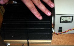
The heatsink is 20 by 17 centimeters...have 15 fins..each one 6 centimeters tall....yes...squared one.
regards,
Carlos
the one.
Also people is using diodes..you can see them searching for a sketch posted earlier in this same thread.
Using fan...or big heatsinks no problems...i have tested them hardly here...and my environment is 29 degrees celsius.
I have used them playing during all day long..normal speaker with pillows over them not to disturb my family.....better than resistive loads is to use the normal complex load...those damn speakers.
The volume was a little less than the distortion threshold...speaker were 4 ohms and voltage was around 19 volts RMS.
I had no problems..the heatsink was enougth...was a 250 watts heatsink.... used in class A Radio Frequency transmitters, the ones operate in class A...and dissipation is 250 watts..the transmitter that used this heatsink had 25 watts of radio frequency over some VHF broadcasting channels.
The temperature was stable after 1 hours of use...i think this test was reasonable...and using a fan you will be more safe.
But if some constructor feel afraid....it is easy to install 3 diodes and a resistance in series to adjust bias...the same bias trimpot can be used and the series resistance substituted by a series of 3 diodes.
Also... a VBE multiplier can be used...i did not have used to make it the most simple possible...of course it will burn under the sunligth in Saara Desert.
The heatsink is 20 by 17 centimeters...have 15 fins..each one 6 centimeters tall....yes...squared one.
regards,
Carlos
Attachments
I have a trick to calculate heatsink size.
This was made under practice... more than fourty years doing, of course, some idea i had created.
My rule is that 100 squared centimeters can hold a standard class AB amplifier runing at maximum undistorted power...it is an aluminium plate of 2 milimeters thick... 10 centimeters side length...squared...resulting 100 squared centimeters.
The heatsink i am showing you...the base dimensions is 20 multiplied by 17...and this result something around 340 squared centimeters.... not precise as you have fins..and those ones stole space in contact with the air...so...the base is not really able to dissipate following the rule i am telling you now....able to 34 watts of dissipation..only the base plate...side multiplied by side...as each 100 square centimeters can hold 10 watts....calculating..you will have 34 watts because this base...
But now lets calculate each fin.... 20 centimeters length and 6 centimeters tall...and they are 15 fins....so.
20 multiplied by 6 and then multiplied by 15 = 1800 is the result.
Now i will use this number in adition with the base...result is 2140 squared centimeters....heatsink is able to 214 watts!
That's the reason it is working fine!....without problems....the amplifier when hard driven is not producing more than 100 watts...total heat there is around 160 watts....the heatsink is over that range.
This method can be usefull for fast calculations...precision is not so big...errors can go bigger than 20 percent...but it is enougth to obtain an idea about.
I will find Mr. Klass heatsink and i will conclude if his heatsink is enougth for my environment.
I will return soon with those informs.
regards,
Carlos
Hi Carlos,
P Robertson might have a point there.
In our part of the World, amplifiers can be much colder when first switched on, so the DX would not perform 'out of the box' so to speak.
Maybe the three diode version would be more useful outside of somewhere that does not get cold.
(Might be worth sticking yours in the fridge and checking the quiescent current as it comes back to your room temperature.)
Cheers ..... Graham.
The output is adjusted, when cold, to 5 miliamps each transistor.
When hot.... after one hour of hard work...when temperature turns stable in my environment, the output..only the output, is draining 40 miliamps each one.
The circuit has more 25 miliamps of consumption, during stand by ... for other circuits.
75 miliamps for the positive rail..because of the zener diode and lower current for the negative rail.
Well Graham...those guys have summer too...and summer temperature matches mine....New York, last year, during summer..i remember very well, as i have a friend in New Jersey, reached 36 Celsius...and i never had so hot weather this way here.
If someone adjust bias to 40 miliamps total each rail..... or 50 to positive and 40 to negative rail...even frozzen, the amplifier will work fine...and better than here, as will never have my hot environment temperature during his foreign winter.
If beautifull Dx amplifier (hehe) can work in my hell hot weather..imagine how cold it will be in yours!
Dx amplifier is prepared to all environment normal temperature, or to be more specific, every environment were humans will feel confortable... there...Dx amplifier will he happy too.
Of course under the sunligth of a desert...inside the car or truck automobile..over the fire or inside Microwave owen, oven... no amplifier will survive for long time.
Also it is not guaranteed against imersion in salt watter...not able to receive inverted tension...not able to resist to fire and cannot run in the bottom of your swiming pool and also will melt if you exposed to Jet airplane exaust gazes....cannot be cooked as a barbecue. hehe
regards,
Carlos🙂
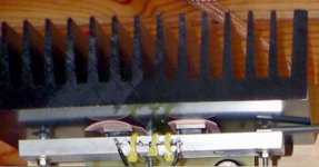
Observing Mr. Klaas heatsink, i have conclude that is a standard 50 watts heatsink
Able to hold 50 watts rms amplifiers...so....will be enougth to dissipate something around 80 watts of heat.
This is good for Dx amplifier using 8 ohms load....Dx amplifier will overheat if used with 4 ohms, even using diodes, with this heatsink...in my environment..if hard driven fo too long time, it may fail.
Heatsink not guaranteed to use under 4 ohms in my environment...maybe in Europe during the winter...
This is an evaluation made only watching..i have not detailed measurements...but seems to be this way observing the size ratio of transistor and the heatsink.
regards,
Carlos
Attachments
You guys have been busy 😎
Just had a quick glance through your posts, a few quick remarks:
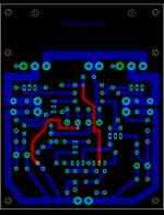
Regarding grounding: i already separated the grounds, look at the backside of my pcb:
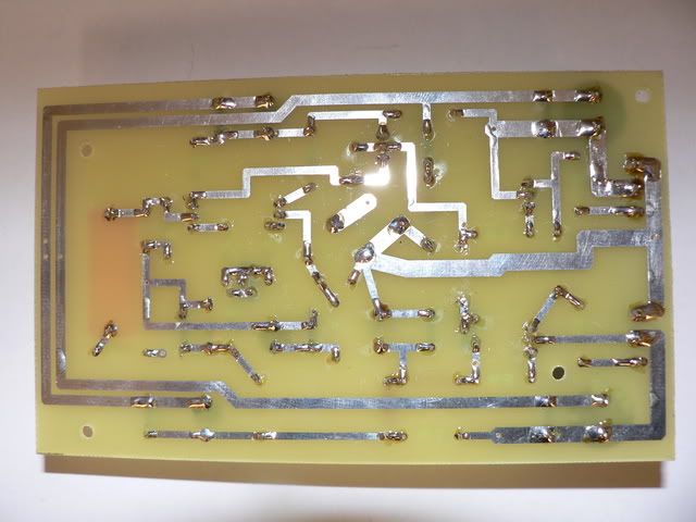
BIG picture is here :
http://i29.photobucket.com/albums/c272/aqvrs1853/P1040666.jpg
There are three separate grounds at the left of the pcb, 2 powergrounds, 1 signal-ground.
I still dont like the long traces for power-grounds, have another eagle-design 'cooking' .
My heatsink is 16x10x4 cm, it is enough for me as i rarely listen loud (i have never fried a tweeter in my life 😉 )
With best regards,
Klaas
Just had a quick glance through your posts, a few quick remarks:
Regarding grounding: i already separated the grounds, look at the backside of my pcb:
BIG picture is here :
http://i29.photobucket.com/albums/c272/aqvrs1853/P1040666.jpg
There are three separate grounds at the left of the pcb, 2 powergrounds, 1 signal-ground.
I still dont like the long traces for power-grounds, have another eagle-design 'cooking' .
My heatsink is 16x10x4 cm, it is enough for me as i rarely listen loud (i have never fried a tweeter in my life 😉 )
With best regards,
Klaas
Well dear Klaas, those ground points will be joined together in some place.
And this point will be your star ground...interesting name...it is the junction of grounding line...made short as possible.
All rigth, and thanks your informations.
Hummmm...nice picture...hehe...i think you turn offended with big fat charlie....do not feel this way ...i am a nice guy.... i made critics to that old picture with losses on focus because i have perceived the good machine you have in the attached image data....you are a good photographer...for sure you are.
regards,
Carlos
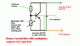
I have perceived people with concerns about the VBE multiplier absence
Was made this way to be simple..to be cheap.
A VBE multiplier can be assembled in a very small board... less than 1 inch side...a squared one..with some copper blocks....you can scratch with a scissor to remove the copper between blocks...or to produce a board (not really needed that perfection..well..your decision).
This small board, with the transistor have to be attached into the heatsink..do not use the BD139 as it will need insulators...it was suggested because tested in simulations only.
This circuit was not constructed real life...but may work...maybe needing small adjustments in the 1K8 resistance.
Use plastic transistors..they do not need insulators...they are better because of that...more easy to use.
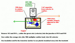
The board will be connected into the board..with wires that may run under the board...and a green wire will be soldered in the junction of R13 and R16.
The orange wire will be soldered at Q3 colector lead...hummm..make those leads as short as possible.
To use the VBE multiplier, Vr2 and R14 have to be removed.
This will turn Dx amplifier a very standard amplifier....not my preference....not my idea...but i will not be happy watching people giving up related construction (quit) because of that.
So..there's the optional circuit show here.
Dx amplifier is made customized to you!
Wanna VBE multiplier?...here is the VBE multiplier to you!
regards,
Carlos
Was made this way to be simple..to be cheap.
A VBE multiplier can be assembled in a very small board... less than 1 inch side...a squared one..with some copper blocks....you can scratch with a scissor to remove the copper between blocks...or to produce a board (not really needed that perfection..well..your decision).
This small board, with the transistor have to be attached into the heatsink..do not use the BD139 as it will need insulators...it was suggested because tested in simulations only.
This circuit was not constructed real life...but may work...maybe needing small adjustments in the 1K8 resistance.
Use plastic transistors..they do not need insulators...they are better because of that...more easy to use.
The board will be connected into the board..with wires that may run under the board...and a green wire will be soldered in the junction of R13 and R16.
The orange wire will be soldered at Q3 colector lead...hummm..make those leads as short as possible.
To use the VBE multiplier, Vr2 and R14 have to be removed.
This will turn Dx amplifier a very standard amplifier....not my preference....not my idea...but i will not be happy watching people giving up related construction (quit) because of that.
So..there's the optional circuit show here.
Dx amplifier is made customized to you!
Wanna VBE multiplier?...here is the VBE multiplier to you!
regards,
Carlos
Attachments
VBE multiplier is only an electronic resistance that will appear between colector and
emitter.
You can see this in the schematic.... those resistor are there to bias the transistor into the conduction...more than 600 milivolts will be measured from base to emitter.
This will turn colector to emitter conductive...and the resistance there will be around 270 ohms....this will produce 2.7 volts that will be divided into four base to emitter junctions..biasing all them.
Those 10 miliamps (aprox.) that will flow from colector to emitter will be the VAS colector to emitter current.
The advantage is that when overheated, this voltage will be reduced and this will protect your circuit against problems of temperature.... output transistors VBE will be reduced...and as a consequence..the colector to emitter current in the output will be also reduced...this is the work VBE multiplier do for us.
Using VBE multiplier you can use small heatsinks.... you can use bad insulators...you can avoid to use fan blowers...well...result in a more reliable amplifier...turning it smaller in size, as big heatsinks will not be needed.
If you wanna small heatsinks!.....Dx amplifier will fit your needs.
The customized amplifier...made for you!
regards,
Carlos
Attachments
Klaas, your heatsink.... from my calculations, is enougth to a 72 watts amplifier.
This way..it will fit your needs under 8 ohms... and exposed to 29 degrees celsius environment..continuous 72 watts tone..a sinusoidal one.
Dinamically triggered HF oscilations use to kill tweeters...Dx amplifier will not oscilate.
It is stable...you can put your wet finger in the input...also 1 meter long aerial and you will not listen to nearby broadcastings.
Also the 10 ohms resistance from the zobel filter will not overheat..meaning that no HF is beeing drained there...if not drained there...HF do not exist.
HF are frequencies inside the Ham radio bands...3 to 30 Megahertz...having bands from 160 to 10 meters .
Also..when we do not use transistors able to oscilate in those frequencies we will be distant from those problems.
regards,
Carlos
Carlos, you're way too fast for me 😀
I did not perceive your remark as an insult, just showing one of my passions -photography.
Capturing beauty in one moment.
To me this amplifier is one for people who don't like instant coffee, but the real thing.
Exploring things, trying things. This topology will not punish you.
Listening to Norah Jones live. Lovely soothing music.
Just remember without music, there would be no amplifiers.
Without amplifiers, there would still be music.
With kind regards,
Klaas
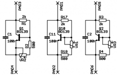
I thought I would post a few PCB options for a vbe circuit on the chance that it may save someone a little work. The circuit and values are from the Symasym amplifier.
My intention was to make the PCB as small as possible so I could mount it directly via the vbe transistor tab onto one of the output devices.
The schematic follows in the next post.
My intention was to make the PCB as small as possible so I could mount it directly via the vbe transistor tab onto one of the output devices.
The schematic follows in the next post.
Attachments
Many thanks by your fast intervenction Greg.
As you have said, values are for symassym....so, will not fit Dx amplifier...as symassym need bigger voltage and different current..so...transistor is biased in another point...i am afraid the trimpot will not reach the correct point of biasing for the Dx amplifier.
But i have post suggested values...those ones, at least were simulated....i do not guarantee simulator results, as sometimes they have failed with me.....maybe some sligth adjustment in resistance values will be needed.... that 1K8 one.
Thanks dear Greg.
.........................................................................................................
Klaas
Dx amplifier is the real thing....not something as instantaneous Coffee.....nice that Klaas... and exactly what i have perceived...you got what i mean...directly in the target.
A realistic amplifier...or stolling from Yamaha...the Natural sound...well..Yamaha have used bootstrapp (alike mine) circuit for hundreds of amplifiers.
It is late...and hot here...very hot... i will sleep..good nigth friends.
regards,
Carlos
Attachments

kvholio said:I still dont like the long traces for power-grounds, have another eagle-design 'cooking' .
hi kvholio and roender,
The initial PCB that was published earlier on, was one of those that follows the schematic layout closely. This PCB was also very close to Carlos's manual prototype. Ths allows quick PCB design and usually ends up with a large board with large component spacing (and a few compremises)... ideal for prototyping and new DIYers.
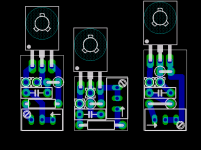
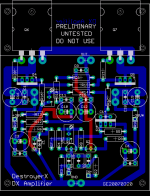
Here is a "early preliminary" version of a PCB that Carlos and I have been working on. I am a little stuck at the moment with the tracks in "red". The main reason I publish an "unfinished" PCB is to show that we are listening and fully understand people's suggestions. It may be of help to you kvholio if you are designing another PCB. You can see a bit of symmetry, the beginnings of a star earth, feedback and output from a centre point between the output transistors, separated power for input and output stages.
Please note the zobel and inductor networks have been removed from the PCB.
Good night Carlos.

regards
Attachments
- Status
- Not open for further replies.
- Home
- Amplifiers
- Solid State
- Destroyer x Amplifier...Dx amp...my amplifier