Member
Joined 2009
Paid Member
I'll have a look, I don't know if I can still find it, I've been doing too many sims and not enough building. But one of the ideas that was party to my explorations was that of pre-distortion and the partial balancing of characteristic curves between devices.
My next thought.
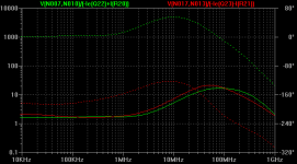
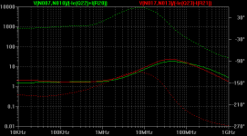
I've been messing around with this CFP driver configuration in the simulator. I suddenly remembered that a while back in the simulator, I discovered that a collector resistor on the slave device improved stability in most applications. I wanted to look at the stability of the CFP's in their current position, so I plotted their output impedance, looking for phase strangeness in the high MHz range (plots show both CFP, complimentary driving output EF). Then I added 100 ohm slave collector resistors. I think it is a healthy improvement. If you're worrying about stability of the CFP, you might want to try this.
The first attached plot is the output impedance of the CFP's without the 100 ohm resistor. The second plot is with. I like the change, although I don't understand the mathematics behind stability much. All I know is that gain should drop off completely after several hundred MHz, instead of rising, and phase should drop too. Usually this is a sign of stability.
EDIT: Sorry, that attachments actually didn't make sense, I goofed up using the simulator.
- keantoken
Last edited:
Okay, here is the real data, and the change isn't as impressive as I once thought. So you can disregard most of what I said in the last post.
The main significance is that this is a very benign way to slow down the CFP. Other ways I've tried always had side effects.
Hmm.
- keantoken
The main significance is that this is a very benign way to slow down the CFP. Other ways I've tried always had side effects.
Hmm.
- keantoken
Attachments
Member
Joined 2009
Paid Member
Well it would be fairly easy to include if I need to.
My notes referred to a William H Gross who put a diode (made out of a transistor) into a CFP but I can't find the internet reference. My circuit was different afterall, it uses a CFP with a diode but some other stuff going on at the same time - it produced lower H3 distortion but it's not ready for prime time yet.
It's a rich area to explore. Another person you could recruit is Wavebourn, he has some interesting stuff going on with diodes and CFP outputs, one of his designs was called 'nuclon'.
I'm not sure how far down this road my brainpower will allow yet. Don't be surprised if you see me with an amplifier this year based around a glass tube....
Member
Joined 2009
Paid Member
Resistors anyone ?
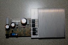
Progress Report: I've started assembling the TGM3 prototype.
So far so good.
Now I have to choose resistors (or links) so do I start as per the schematic, or do I start by putting in links for the CFP internal degeneration....?
Progress Report: I've started assembling the TGM3 prototype.
So far so good.
Now I have to choose resistors (or links) so do I start as per the schematic, or do I start by putting in links for the CFP internal degeneration....?
Attachments
Last edited:
Just put resistors on the PNP side for now. 
You can put the resistors in AND bypass them with wires, later on just cut the wires.
- keantoken
You can put the resistors in AND bypass them with wires, later on just cut the wires.
- keantoken
Member
Joined 2009
Paid Member
For the PNP side (as opposed to the NPN side) do I put the resistors in the other way around, with the gold stripe facing forwards ?
😀
😀
No, the gold strip should always face the same direction - to promote 2nd harmonics. 😉
- keantoken
- keantoken
Member
Joined 2009
Paid Member
Is that a tube I see ??? Bigun I have a document you should read about the effects of the harmonics. This was written by a tube designer, everything is not always so rosy when you push a amp to just have 2nd harmonics. He s opinion is that an amp, tubes only in his case, with a overwhelming or only second harmonic content do not sound too good either. He came up with a clever and simple way to easily change his tube amplifier s harmonic distortion spectrum so that he could do comparisons. I cant remember exactly how he did it, i only read that part fleetingly and was more interested in his opinion about how harmonics affect the sound. I just need a couple of days to search for the document as it was quite a while back and is somewhere on my backup drives which are in storage.
Member
Joined 2009
Paid Member
Yup, glass it is. Mind you, it's not really on my agenda just because I may want 2nd harmonics, I have figured out how to make as many of those as I want already - this issue is avoiding those higher order odd harmonics. But I keep hearing about tubes and I'm in this hobby to explore not make the best SS amplifier or a commercial one.... so I need to make a tube amplifier to round out the experience and I'd be quite interested to learn more about the effects of harmonics if you can dig up that article.
Talking of old technology, a British band called "The Men That Will Not Be Blamed For Nothing" are releasing one of their new singles on a wax cylinder next month, for use with a phonogram. WOW !
Talking of old technology, a British band called "The Men That Will Not Be Blamed For Nothing" are releasing one of their new singles on a wax cylinder next month, for use with a phonogram. WOW !
Aww, but I'll be lonely out here in SS world! I've been asking around to see if I can get a good tube amp, no avail. I've got plenty Tektronix type tubes, and come to think about it I also have some speaker transformers... Banish the thought! I'm afraid to fire up that crusty dirt-caked HV transformer...
I went back in threads and revisited an old friend... The best sound I ever heard came from this amp. Allison with CFP's, no less! Incredibly unstable! It was hell with a power cord... But the music came from heaven... So it seems there really is no free lunch in this world. You get out what you put in, nothing more, nothing less. (the amplifier is flawless in a theoretical sense, but in fact I think I was overbiasing the LTP and creating 2nd harmonics! Imagine that...)
http://www.diyaudio.com/forums/solid-state/137240-6w-class-hopefully-something-i-can-build-d-2.html
Homemodder! I am also interested in this paper!
Think you have a copy for me?
Bigun - It just occurred to me that, since it is the master in the CFP that controls feedback, that putting a local Cdom on the master may be the best way to stabilize it. Give the Master a collector resistor, say 100 ohms, and then put a small cap across B-C. Will simulate...
- keantoken
I tried the option I mentioned previously in the simulator. It didn't work quite well enough I thought, since too much compensation caused phase strangeness. It seems all we can do is slow the CFP down using a lowpass RC filter in front.
It seems like the stability of the CFP is very dependent on what it's hooked up to. One thing I've noticed is that circuits that can pump a lot of power, very fast, tend to cause others to oscillate. It's very high transconductance may cause difficulties too. Perhaps the CFP is just too fast? For example, Klewis had oscillations when using fast drivers for MJL1302A type devices, but the circuit was stable when he downgraded to slower devices.
However, you are using rather fast output devices, so it may be fine.
Perhaps the simulator just isn't complex enough to find the troubles? (I have had similar things happen in my simulations however)
EDIT: The most benign way to slow down (and presumably stabilize) the CFP is to give the slave device a local Cdom. I would suggest over 100pF to start with.
- keantoken
Last edited:
Why is it that the CFP simulates blamelessly and yet everyone has problems with it in the real world?
- keantoken
- keantoken
Member
Joined 2009
Paid Member
The simulator does not account for the parasitics within the devices and due to the pcb layout which are much more relevant at the high frequencies these oscillations are seen.
I've powered up the board. Doesn't work. dc offset -2V, no current flow through the output devices. I think the input had a short which I've now cleared. Now too much current flows through the output devices. The struggle begins.....
I've powered up the board. Doesn't work. dc offset -2V, no current flow through the output devices. I think the input had a short which I've now cleared. Now too much current flows through the output devices. The struggle begins.....
Member
Joined 2009
Paid Member
Operating conitions seem to have been restored with dc currents all checked out, but the amp is blowing fuses. It's drawing a lot more current than the voltage drops across resistors says that it is. That current doesn't seem to be showing up in the dc analysis.
but - the zobel resistor is very hot, oscillations I presume Mr Watson, time to break out the CRO
but - the zobel resistor is very hot, oscillations I presume Mr Watson, time to break out the CRO
Yes, Gareth, oscillation......
Try EITHER reducing OLG, OR increasing lag comp, OR introducing phase lead.
Once the oscillations are fixed, examine carefully on a CRO for overshoot with square wave, then, let the listening tests begin.....
Hugh
Try EITHER reducing OLG, OR increasing lag comp, OR introducing phase lead.
Once the oscillations are fixed, examine carefully on a CRO for overshoot with square wave, then, let the listening tests begin.....
Hugh
Have you tried the lightbulb thing? Maybe I'm just cheap, but I hate wasting fuses.
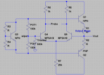
I came up with this circuit the other day, wondering how, in real life, one might adjust output EF bias with some feedback. This way, you can watch on the scope the output distortion and adjust the bias perfectly.
This is my idea. Adjust the 200k POT (two 100k resistors) until DC the LTP is balanced, and then adjust the 500k POT until you can see the OP distortion clearly. Now you can adjust bias until the trace disappears. (divider values are large to keep from loading the VAS)
I thought you may be interested and have the ability to test it out (I don't see why it wouldn't work). Apart from the common bias point around 100mA, you might want to try find the Null point, in the simulator it is usually above 200mA (however I think I remember that emitter resistors ruined this possibility). This point gives much lower distortion.
I know you already have a lot of things you will try, It's your call.
- keantoken
Attachments
Member
Joined 2009
Paid Member
I was expecting to see oscillations above 1MHz but instead they measure at 125kHz.
Increasing Cdom to 47uF killed the oscillations so at least that gives a data point!
Increasing Cdom to 136pF was ineffective, even with 100R emitter degeneration added to the input device/error amplifier. Phase lead of 22pF also ineffective. More drastic values are not likely to be good for sonics. I will take another look tomorrow and consider some capacitance between B-C on the pre-driver (although 22pF was ineffective when tried). It's reputed to kill the sonics if a large value is needed here.
Edit: Kean, just saw your post. It looks interesting, but I don't have an LTP on this design to try that. I took out the fuses - the fulse holders are paralleled with 10R power resistors, a kind of poor mans light bulb. But even with this, the zobel gets hot fast so I turn on, measure, turn off. The CRO shows the oscillations very clearly so it's pretty convenient. It's quite exciting, I never had much trouble with the other TGMs so this is my first time to have a play with something less cooperative.
Last edited:
- Status
- Not open for further replies.
- Home
- Amplifiers
- Solid State
- designing TGM3 - output Triples