Member
Joined 2009
Paid Member
If you are referring to the degeneration I've included inside the CFP ? - the design I've used allows for the use of a number of additional resistors due to a lack of confidence in my part that things will work just fine without them because of the limitations of Spice to capture parasitics etc.. I've tried to include resistors in the same locations that Quad did in their model 303 amplifier. They are easy enough to replace with links if they are found unnecessary for stability; on the other hand I don't expect them to detract very much from the sonics.
For the first prototype at least, the topology is fixed and the challenge now is to make it work with some flexibility on component values.
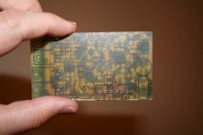
I managed to find a piece of scrap pcb that was almost wide enough to fit - and decided to use it anyway...
For the first prototype at least, the topology is fixed and the challenge now is to make it work with some flexibility on component values.
I managed to find a piece of scrap pcb that was almost wide enough to fit - and decided to use it anyway...
Attachments
I think the primary effect of degeneration here is slowing down the ordinarily steep turn on/off event of sensitive devices. The significance is that when the switching is slowed down, less higher harmonics are generated which stresses the amp less. (the feedback mechanism responds more for higher frequencies, since it must pump power through Cdom and other compensation - this brings the devices farther out of their nominal operating range)
However if the CFP's are biased so they don't switch off, we can avoid the resistors altogether (are the resistors necessary in the first place, though?). I don't really know what good this does though, the CFP's are already beyond reproach if you look at the disaster that comes after them - the outputs generate most of the distortion. This takes form not in current through the VAS, but through the input voltage of the output stage. This voltage distortion goes through Cdom. If we could somehow put Cdom after the outputs instead of before, we would avoid injecting evil crossover harmonics through the feedback loop.
Oops, I've started rambling.
Parting thought:
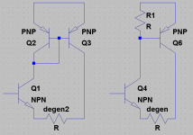
Degenerating the master device of a CFP will inject distortion from the slave's B-E resistor resulting from nonlinear Vbe transfer curve. In a very old thread I discovered I had accidentally designed a pseudo-CFP. I think perhaps the design could be revisited with some benefit. This way, degenerating the master device injects minimal distortion. I'll do some simulations. Seems kind of silly to me but I'll do it anyways.
Adding a whole new transistor is probably one of the last things we want, but I think it can be replaced with a diode.
- keantoken
However if the CFP's are biased so they don't switch off, we can avoid the resistors altogether (are the resistors necessary in the first place, though?). I don't really know what good this does though, the CFP's are already beyond reproach if you look at the disaster that comes after them - the outputs generate most of the distortion. This takes form not in current through the VAS, but through the input voltage of the output stage. This voltage distortion goes through Cdom. If we could somehow put Cdom after the outputs instead of before, we would avoid injecting evil crossover harmonics through the feedback loop.
Oops, I've started rambling.
Parting thought:
Degenerating the master device of a CFP will inject distortion from the slave's B-E resistor resulting from nonlinear Vbe transfer curve. In a very old thread I discovered I had accidentally designed a pseudo-CFP. I think perhaps the design could be revisited with some benefit. This way, degenerating the master device injects minimal distortion. I'll do some simulations. Seems kind of silly to me but I'll do it anyways.
Adding a whole new transistor is probably one of the last things we want, but I think it can be replaced with a diode.
- keantoken
Attachments
Member
Joined 2009
Paid Member
That's a good point, Quad had the additional risk of instability because they did not use a Self Type II EF output which would protect the CFP's from switching off. In this case I might find I can simply remove R23 & R24.
I'm hoping to re-use parts from the now rejected TGM1 to build it but I'm not sure how easily they'll come off the old pcb yet.
I'm hoping to re-use parts from the now rejected TGM1 to build it but I'm not sure how easily they'll come off the old pcb yet.
Member
Joined 2009
Paid Member
No degeneration yet.
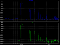
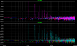
Here is a plot stepping from 5, 10, 15, and 20 ohms degeneration. The affect on the less conventional CFP is practically nonexistant, but for the conventional CFP distortion indeed increases with degeneration.
Really the new thing just doubles the transconductance of the transistor... Add another PNP parallel to Q3 and you'd have triple. Hmm.
- keantoken
Attachments
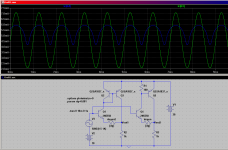
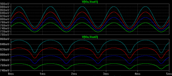
Here is the difference between Vin and Vout for both types, with aforementioned degeneration steps.
At first I felt silly for considering this option - it gives back so little for what you put into it compared with what I would usually put in its place. However this is just from the point of view that OLG fixes everything. In fact, all we need to drive the outputs is a buffer, and the only purpose of a buffer is to provide current gain. In all other respects it should be transparent and not inject anything harmful. In this respect I'm starting to like the idea.
Setting harmonic profile aside, distortion for the new type is .01% more.
- keantoken
Attachments
Member
Joined 2009
Paid Member
This makes sense, the degeneration is reducing the OLG of the CFP.
Adding another device isn't on the cards at this point because I have a pcb ready to go but the idea looks very interesting (you should look at the Bryston Triple for further interest) - so for the first prototype the choice is degeneration or no degeneration - will I be able to hear any difference ? does degeneration inside the CFP pair improve device mis-match between the pairs ?
edit: to clarify, the two plots you've just posted, the top one has a triple as the driver, the lower has the CFP with internal degen ?
Last edited:
This makes sense, the degeneration is reducing the OLG of the CFP.
Actually, this breaks down when you consider that, were the current through R1 linear, degeneration would not decrease distortion (as my modification proves). Degenerating the master doesn't decrease OLG; it just decreases gain. To decrease OLG you would degenerate the slave (though I don't think you were talking about this). The master simply sets the gain from input to output. (now that I think about it, if anything, it is the master that must linearize the slave! It's the master that applies negative feedback to the slave)
Looking at the CFP I now realize there really isn't any special negative feedback in the configuration in the sense normally thought. The slave device simply divides the current through the master and so multiplies it's gain. The voltage applied to the master's emitter tends to be considered as feedback. However, the transistor alone has this same mechanism; the emitter current produces a voltage at the emitter that acts as local feedback. All the CFP does is economize the untapped collector current and multiply what was already there in the first place.
It's not the slave which acts to linearize the master, it's the other way around!!!! We've been thinking about it all backwards!!!
!!!
!!!
Thinking this way takes some of the mysticism out of the CFP and presents it in a way that's realistic for all our observations. We also see that the CFP is not so innocent...
You don't need to add a whole new transistor - simply replace R1 (in my schematic) with a diode.Adding another device isn't on the cards at this point because I have a pcb ready to go but the idea looks very interesting (you should look at the Bryston Triple for further interest) - so for the first prototype the choice is degeneration or no degeneration - will I be able to hear any difference ? does degeneration inside the CFP pair improve device mis-match between the pairs ?
edit: to clarify, the two plots you've just posted, the top one has a triple as the driver, the lower has the CFP with internal degen ?
Yes.
- keantoken
Last edited:
Hey, look at this!
The CFP without degeneration has less THD than my modification, but the instant degeneration is applied, it is actually worse!
The pattern continues, and we also discover, that for my modification THD in fact decreases with increasing degeneration.
- keantoken
The CFP without degeneration has less THD than my modification, but the instant degeneration is applied, it is actually worse!
.step dg=0.001
Direct Newton iteration for .op point succeeded.
Fourier components of V(vout1)
DC component:9.27355
Harmonic Frequency Fourier Normalized Phase Normalized
Number [Hz] Component Component [degree] Phase [deg]
1 1.000e+03 4.983e+00 1.000e+00 -0.00° 0.00°
2 2.000e+03 2.167e-03 4.349e-04 -89.96° -89.96°
3 3.000e+03 4.240e-04 8.508e-05 0.08° 0.08°
4 4.000e+03 9.200e-05 1.846e-05 90.10° 90.10°
5 5.000e+03 2.132e-05 4.278e-06 -179.86° -179.86°
6 6.000e+03 5.148e-06 1.033e-06 -89.86° -89.86°
7 7.000e+03 1.262e-06 2.532e-07 0.23° 0.23°
8 8.000e+03 3.079e-07 6.179e-08 96.00° 96.00°
9 9.000e+03 8.434e-08 1.693e-08 176.05° 176.05°
Total Harmonic Distortion: 0.044353%
Fourier components of V(vout2)
DC component:9.26728
Harmonic Frequency Fourier Normalized Phase Normalized
Number [Hz] Component Component [degree] Phase [deg]
1 1.000e+03 4.995e+00 1.000e+00 -0.00° 0.00°
2 2.000e+03 1.509e-03 3.022e-04 -89.98° -89.98°
3 3.000e+03 7.193e-04 1.440e-04 0.03° 0.03°
4 4.000e+03 3.326e-04 6.659e-05 90.01° 90.01°
5 5.000e+03 1.423e-04 2.849e-05 179.98° 179.98°
6 6.000e+03 5.239e-05 1.049e-05 -90.06° -90.06°
7 7.000e+03 1.355e-05 2.714e-06 -0.24° -0.24°
8 8.000e+03 7.386e-07 1.479e-07 -86.09° -86.09°
9 9.000e+03 4.192e-06 8.392e-07 -0.04° -0.04°
Total Harmonic Distortion: 0.034264%
.step dg=5
Fourier components of V(vout1)
DC component:9.25058
Harmonic Frequency Fourier Normalized Phase Normalized
Number [Hz] Component Component [degree] Phase [deg]
1 1.000e+03 4.971e+00 1.000e+00 -0.00° 0.00°
2 2.000e+03 2.105e-03 4.235e-04 -89.97° -89.97°
3 3.000e+03 4.234e-04 8.518e-05 0.10° 0.10°
4 4.000e+03 9.180e-05 1.847e-05 90.11° 90.11°
5 5.000e+03 2.126e-05 4.276e-06 -179.87° -179.87°
6 6.000e+03 5.111e-06 1.028e-06 -89.64° -89.64°
7 7.000e+03 1.282e-06 2.579e-07 0.23° 0.23°
8 8.000e+03 3.162e-07 6.361e-08 92.12° 92.12°
9 9.000e+03 8.228e-08 1.655e-08 168.70° 168.70°
Total Harmonic Distortion: 0.043241%
Fourier components of V(vout2)
DC component:9.24021
Harmonic Frequency Fourier Normalized Phase Normalized
Number [Hz] Component Component [degree] Phase [deg]
1 1.000e+03 4.991e+00 1.000e+00 -0.00° 0.00°
2 2.000e+03 2.906e-03 5.823e-04 -89.99° -89.99°
3 3.000e+03 1.340e-03 2.685e-04 0.03° 0.03°
4 4.000e+03 5.996e-04 1.201e-04 90.00° 90.00°
5 5.000e+03 2.444e-04 4.897e-05 179.96° 179.96°
6 6.000e+03 8.196e-05 1.642e-05 -90.10° -90.10°
7 7.000e+03 1.525e-05 3.055e-06 -0.41° -0.41°
8 8.000e+03 6.827e-06 1.368e-06 -89.26° -89.26°
9 9.000e+03 1.036e-05 2.076e-06 0.19° 0.19°
Total Harmonic Distortion: 0.065441%
The pattern continues, and we also discover, that for my modification THD in fact decreases with increasing degeneration.
.step dg=10
Fourier components of V(vout1)
DC component:9.22771
Harmonic Frequency Fourier Normalized Phase Normalized
Number [Hz] Component Component [degree] Phase [deg]
1 1.000e+03 4.958e+00 1.000e+00 -0.00° 0.00°
2 2.000e+03 2.044e-03 4.122e-04 -89.98° -89.98°
3 3.000e+03 4.228e-04 8.528e-05 0.11° 0.11°
4 4.000e+03 9.160e-05 1.848e-05 90.10° 90.10°
5 5.000e+03 2.120e-05 4.276e-06 -179.80° -179.80°
6 6.000e+03 5.110e-06 1.031e-06 -89.97° -89.97°
7 7.000e+03 1.280e-06 2.582e-07 0.84° 0.84°
8 8.000e+03 3.459e-07 6.976e-08 89.86° 89.86°
9 9.000e+03 6.584e-08 1.328e-08 176.52° 176.52°
Total Harmonic Distortion: 0.042140%
Fourier components of V(vout2)
DC component:9.21321
Harmonic Frequency Fourier Normalized Phase Normalized
Number [Hz] Component Component [degree] Phase [deg]
1 1.000e+03 4.987e+00 1.000e+00 -0.00° 0.00°
2 2.000e+03 4.340e-03 8.703e-04 -89.99° -89.99°
3 3.000e+03 1.978e-03 3.966e-04 0.02° 0.02°
4 4.000e+03 8.715e-04 1.747e-04 90.00° 90.00°
5 5.000e+03 3.459e-04 6.936e-05 179.96° 179.96°
6 6.000e+03 1.093e-04 2.191e-05 -90.14° -90.14°
7 7.000e+03 1.477e-05 2.961e-06 -0.68° -0.68°
8 8.000e+03 1.442e-05 2.891e-06 -89.51° -89.51°
9 9.000e+03 1.726e-05 3.460e-06 0.10° 0.10°
Total Harmonic Distortion: 0.097498%
.step dg=15
Fourier components of V(vout1)
DC component:9.20496
Harmonic Frequency Fourier Normalized Phase Normalized
Number [Hz] Component Component [degree] Phase [deg]
1 1.000e+03 4.946e+00 1.000e+00 -0.00° 0.00°
2 2.000e+03 1.984e-03 4.011e-04 -89.99° -89.99°
3 3.000e+03 4.223e-04 8.539e-05 0.13° 0.13°
4 4.000e+03 9.143e-05 1.849e-05 90.09° 90.09°
5 5.000e+03 2.115e-05 4.276e-06 -179.75° -179.75°
6 6.000e+03 5.117e-06 1.035e-06 -89.77° -89.77°
7 7.000e+03 1.270e-06 2.568e-07 0.47° 0.47°
8 8.000e+03 3.058e-07 6.183e-08 94.54° 94.54°
9 9.000e+03 7.353e-08 1.487e-08 174.52° 174.52°
Total Harmonic Distortion: 0.041052%
Fourier components of V(vout2)
DC component:9.18626
Harmonic Frequency Fourier Normalized Phase Normalized
Number [Hz] Component Component [degree] Phase [deg]
1 1.000e+03 4.983e+00 1.000e+00 -0.00° 0.00°
2 2.000e+03 5.812e-03 1.166e-03 -89.99° -89.99°
3 3.000e+03 2.632e-03 5.281e-04 0.02° 0.02°
4 4.000e+03 1.148e-03 2.303e-04 89.99° 89.99°
5 5.000e+03 4.463e-04 8.956e-05 179.96° 179.96°
6 6.000e+03 1.340e-04 2.689e-05 -90.16° -90.16°
7 7.000e+03 1.197e-05 2.402e-06 -1.12° -1.12°
8 8.000e+03 2.349e-05 4.713e-06 -89.70° -89.70°
9 9.000e+03 2.492e-05 5.000e-06 0.04° 0.04°
Total Harmonic Distortion: 0.130422%
.step dg=20
Fourier components of V(vout1)
DC component:9.18233
Harmonic Frequency Fourier Normalized Phase Normalized
Number [Hz] Component Component [degree] Phase [deg]
1 1.000e+03 4.933e+00 1.000e+00 -0.00° 0.00°
2 2.000e+03 1.924e-03 3.901e-04 -90.01° -90.00°
3 3.000e+03 4.217e-04 8.549e-05 0.14° 0.14°
4 4.000e+03 9.123e-05 1.849e-05 90.09° 90.09°
5 5.000e+03 2.113e-05 4.284e-06 -179.76° -179.76°
6 6.000e+03 5.069e-06 1.028e-06 -89.56° -89.56°
7 7.000e+03 1.276e-06 2.586e-07 -1.24° -1.24°
8 8.000e+03 3.180e-07 6.446e-08 91.48° 91.48°
9 9.000e+03 6.127e-08 1.242e-08 171.12° 171.12°
Total Harmonic Distortion: 0.039978%
Fourier components of V(vout2)
DC component:9.15936
Harmonic Frequency Fourier Normalized Phase Normalized
Number [Hz] Component Component [degree] Phase [deg]
1 1.000e+03 4.979e+00 1.000e+00 -0.00° 0.00°
2 2.000e+03 7.321e-03 1.470e-03 -89.99° -89.99°
3 3.000e+03 3.301e-03 6.630e-04 0.02° 0.02°
4 4.000e+03 1.427e-03 2.867e-04 89.99° 89.99°
5 5.000e+03 5.453e-04 1.095e-04 179.95° 179.95°
6 6.000e+03 1.559e-04 3.130e-05 -90.17° -90.17°
7 7.000e+03 6.774e-06 1.360e-06 -2.65° -2.65°
8 8.000e+03 3.411e-05 6.850e-06 -89.74° -89.74°
9 9.000e+03 3.327e-05 6.682e-06 0.01° 0.01°
Total Harmonic Distortion: 0.164210%
- keantoken
Alright!
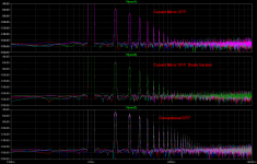
To be thorough, I added a variation that uses just a diode instead of a whole new transistor.
Higher power devices such as the 2SA1837 often have lower Vbe. Because of this, the diode doesn't match it as well and in fact gives it gain instead of being an honest current mirror.
The simulations suggest that this version, as well as being more convenient, seems to have the best of both worlds. Steep decreasing line of harmonics with no strangeness, lowest distortion, high transconductance and distortion increases only very slightly with increasing degeneration.
I just wish there was a way to hide large blocks of text so I don't clutter up the forum...
- keantoken
To be thorough, I added a variation that uses just a diode instead of a whole new transistor.
Higher power devices such as the 2SA1837 often have lower Vbe. Because of this, the diode doesn't match it as well and in fact gives it gain instead of being an honest current mirror.
The simulations suggest that this version, as well as being more convenient, seems to have the best of both worlds. Steep decreasing line of harmonics with no strangeness, lowest distortion, high transconductance and distortion increases only very slightly with increasing degeneration.
.step dg=0.001
Direct Newton iteration for .op point succeeded.
Fourier components of V(vout1)
DC component:9.27355
Harmonic Frequency Fourier Normalized Phase Normalized
Number [Hz] Component Component [degree] Phase [deg]
1 1.000e+03 4.983e+00 1.000e+00 -0.00° 0.00°
2 2.000e+03 2.167e-03 4.349e-04 -89.96° -89.96°
3 3.000e+03 4.240e-04 8.508e-05 0.08° 0.08°
4 4.000e+03 9.199e-05 1.846e-05 90.10° 90.10°
5 5.000e+03 2.133e-05 4.280e-06 -179.82° -179.82°
6 6.000e+03 5.111e-06 1.026e-06 -89.89° -89.89°
7 7.000e+03 1.298e-06 2.605e-07 -0.19° -0.19°
8 8.000e+03 3.289e-07 6.601e-08 88.87° 88.87°
9 9.000e+03 7.967e-08 1.599e-08 -176.55° -176.55°
Total Harmonic Distortion: 0.044353%
Fourier components of V(vout2)
DC component:9.26728
Harmonic Frequency Fourier Normalized Phase Normalized
Number [Hz] Component Component [degree] Phase [deg]
1 1.000e+03 4.995e+00 1.000e+00 -0.00° 0.00°
2 2.000e+03 1.509e-03 3.022e-04 -89.98° -89.98°
3 3.000e+03 7.193e-04 1.440e-04 0.03° 0.03°
4 4.000e+03 3.326e-04 6.658e-05 90.01° 90.01°
5 5.000e+03 1.424e-04 2.850e-05 179.99° 179.99°
6 6.000e+03 5.238e-05 1.049e-05 -90.09° -90.09°
7 7.000e+03 1.355e-05 2.712e-06 -0.27° -0.27°
8 8.000e+03 7.423e-07 1.486e-07 -87.18° -87.18°
9 9.000e+03 4.186e-06 8.380e-07 0.38° 0.38°
Total Harmonic Distortion: 0.034264%
Fourier components of V(vout3)
DC component:9.31089
Harmonic Frequency Fourier Normalized Phase Normalized
Number [Hz] Component Component [degree] Phase [deg]
1 1.000e+03 4.987e+00 1.000e+00 -0.00° 0.00°
2 2.000e+03 1.680e-03 3.370e-04 -89.81° -89.81°
3 3.000e+03 3.289e-04 6.596e-05 0.35° 0.35°
4 4.000e+03 7.144e-05 1.433e-05 90.39° 90.39°
5 5.000e+03 1.652e-05 3.313e-06 -179.46° -179.46°
6 6.000e+03 3.987e-06 7.996e-07 -89.34° -89.34°
7 7.000e+03 1.015e-06 2.036e-07 0.67° 0.67°
8 8.000e+03 2.321e-07 4.655e-08 93.00° 93.00°
9 9.000e+03 7.129e-08 1.430e-08 178.92° 178.92°
Total Harmonic Distortion: 0.034371%
.step dg=5
Fourier components of V(vout1)
DC component:9.25058
Harmonic Frequency Fourier Normalized Phase Normalized
Number [Hz] Component Component [degree] Phase [deg]
1 1.000e+03 4.971e+00 1.000e+00 -0.00° 0.00°
2 2.000e+03 2.105e-03 4.235e-04 -89.97° -89.97°
3 3.000e+03 4.234e-04 8.518e-05 0.10° 0.10°
4 4.000e+03 9.181e-05 1.847e-05 90.11° 90.11°
5 5.000e+03 2.124e-05 4.274e-06 -179.89° -179.89°
6 6.000e+03 5.131e-06 1.032e-06 -89.80° -89.80°
7 7.000e+03 1.276e-06 2.567e-07 0.29° 0.29°
8 8.000e+03 3.270e-07 6.579e-08 92.22° 92.22°
9 9.000e+03 8.714e-08 1.753e-08 163.66° 163.66°
Total Harmonic Distortion: 0.043240%
Fourier components of V(vout2)
DC component:9.24021
Harmonic Frequency Fourier Normalized Phase Normalized
Number [Hz] Component Component [degree] Phase [deg]
1 1.000e+03 4.991e+00 1.000e+00 -0.00° 0.00°
2 2.000e+03 2.906e-03 5.823e-04 -89.99° -89.99°
3 3.000e+03 1.340e-03 2.685e-04 0.03° 0.03°
4 4.000e+03 5.996e-04 1.201e-04 90.00° 90.00°
5 5.000e+03 2.444e-04 4.897e-05 179.96° 179.96°
6 6.000e+03 8.200e-05 1.643e-05 -90.11° -90.11°
7 7.000e+03 1.524e-05 3.053e-06 -0.47° -0.47°
8 8.000e+03 6.838e-06 1.370e-06 -89.47° -89.47°
9 9.000e+03 1.037e-05 2.078e-06 0.19° 0.19°
Total Harmonic Distortion: 0.065441%
Fourier components of V(vout3)
DC component:9.3055
Harmonic Frequency Fourier Normalized Phase Normalized
Number [Hz] Component Component [degree] Phase [deg]
1 1.000e+03 4.984e+00 1.000e+00 -0.00° 0.00°
2 2.000e+03 1.738e-03 3.486e-04 -89.83° -89.83°
3 3.000e+03 3.372e-04 6.766e-05 0.36° 0.36°
4 4.000e+03 7.273e-05 1.459e-05 90.37° 90.37°
5 5.000e+03 1.676e-05 3.362e-06 -179.46° -179.46°
6 6.000e+03 4.037e-06 8.099e-07 -89.24° -89.24°
7 7.000e+03 1.027e-06 2.061e-07 0.87° 0.87°
8 8.000e+03 2.505e-07 5.027e-08 90.79° 90.79°
9 9.000e+03 7.776e-08 1.560e-08 175.42° 175.42°
Total Harmonic Distortion: 0.035547%
.step dg=10
Fourier components of V(vout1)
DC component:9.22771
Harmonic Frequency Fourier Normalized Phase Normalized
Number [Hz] Component Component [degree] Phase [deg]
1 1.000e+03 4.958e+00 1.000e+00 -0.00° 0.00°
2 2.000e+03 2.044e-03 4.122e-04 -89.98° -89.98°
3 3.000e+03 4.229e-04 8.529e-05 0.12° 0.12°
4 4.000e+03 9.161e-05 1.848e-05 90.09° 90.09°
5 5.000e+03 2.120e-05 4.277e-06 -179.85° -179.85°
6 6.000e+03 5.106e-06 1.030e-06 -89.81° -89.81°
7 7.000e+03 1.277e-06 2.576e-07 1.03° 1.03°
8 8.000e+03 3.253e-07 6.562e-08 87.39° 87.39°
9 9.000e+03 6.887e-08 1.389e-08 178.41° 178.41°
Total Harmonic Distortion: 0.042140%
Fourier components of V(vout2)
DC component:9.21321
Harmonic Frequency Fourier Normalized Phase Normalized
Number [Hz] Component Component [degree] Phase [deg]
1 1.000e+03 4.987e+00 1.000e+00 -0.00° 0.00°
2 2.000e+03 4.340e-03 8.703e-04 -89.99° -89.99°
3 3.000e+03 1.978e-03 3.966e-04 0.02° 0.02°
4 4.000e+03 8.714e-04 1.747e-04 89.99° 89.99°
5 5.000e+03 3.459e-04 6.936e-05 179.96° 179.96°
6 6.000e+03 1.093e-04 2.191e-05 -90.12° -90.12°
7 7.000e+03 1.477e-05 2.962e-06 -0.77° -0.77°
8 8.000e+03 1.440e-05 2.887e-06 -89.68° -89.68°
9 9.000e+03 1.726e-05 3.460e-06 0.07° 0.07°
Total Harmonic Distortion: 0.097498%
Fourier components of V(vout3)
DC component:9.30013
Harmonic Frequency Fourier Normalized Phase Normalized
Number [Hz] Component Component [degree] Phase [deg]
1 1.000e+03 4.982e+00 1.000e+00 -0.00° 0.00°
2 2.000e+03 1.795e-03 3.603e-04 -89.84° -89.84°
3 3.000e+03 3.455e-04 6.935e-05 0.37° 0.37°
4 4.000e+03 7.402e-05 1.486e-05 90.36° 90.36°
5 5.000e+03 1.705e-05 3.423e-06 -179.34° -179.34°
6 6.000e+03 4.084e-06 8.197e-07 -89.50° -89.50°
7 7.000e+03 1.014e-06 2.035e-07 -0.22° -0.22°
8 8.000e+03 2.475e-07 4.967e-08 94.43° 94.43°
9 9.000e+03 6.277e-08 1.260e-08 179.69° 179.69°
Total Harmonic Distortion: 0.036722%
.step dg=15
Fourier components of V(vout1)
DC component:9.20496
Harmonic Frequency Fourier Normalized Phase Normalized
Number [Hz] Component Component [degree] Phase [deg]
1 1.000e+03 4.946e+00 1.000e+00 -0.00° 0.00°
2 2.000e+03 1.984e-03 4.011e-04 -89.99° -89.99°
3 3.000e+03 4.223e-04 8.539e-05 0.13° 0.13°
4 4.000e+03 9.142e-05 1.848e-05 90.10° 90.10°
5 5.000e+03 2.117e-05 4.281e-06 -179.81° -179.81°
6 6.000e+03 5.094e-06 1.030e-06 -89.84° -89.84°
7 7.000e+03 1.260e-06 2.548e-07 0.36° 0.37°
8 8.000e+03 3.296e-07 6.665e-08 92.97° 92.97°
9 9.000e+03 7.002e-08 1.416e-08 158.95° 158.95°
Total Harmonic Distortion: 0.041052%
Fourier components of V(vout2)
DC component:9.18626
Harmonic Frequency Fourier Normalized Phase Normalized
Number [Hz] Component Component [degree] Phase [deg]
1 1.000e+03 4.983e+00 1.000e+00 -0.00° 0.00°
2 2.000e+03 5.812e-03 1.166e-03 -89.99° -89.99°
3 3.000e+03 2.632e-03 5.281e-04 0.02° 0.02°
4 4.000e+03 1.148e-03 2.303e-04 89.99° 89.99°
5 5.000e+03 4.463e-04 8.956e-05 179.95° 179.95°
6 6.000e+03 1.340e-04 2.689e-05 -90.15° -90.15°
7 7.000e+03 1.201e-05 2.409e-06 -1.25° -1.25°
8 8.000e+03 2.349e-05 4.714e-06 -89.75° -89.75°
9 9.000e+03 2.493e-05 5.004e-06 0.12° 0.12°
Total Harmonic Distortion: 0.130422%
Fourier components of V(vout3)
DC component:9.29475
Harmonic Frequency Fourier Normalized Phase Normalized
Number [Hz] Component Component [degree] Phase [deg]
1 1.000e+03 4.980e+00 1.000e+00 -0.00° 0.00°
2 2.000e+03 1.852e-03 3.719e-04 -89.86° -89.86°
3 3.000e+03 3.538e-04 7.104e-05 0.37° 0.37°
4 4.000e+03 7.533e-05 1.513e-05 90.35° 90.35°
5 5.000e+03 1.724e-05 3.461e-06 -179.28° -179.28°
6 6.000e+03 4.138e-06 8.310e-07 -89.01° -89.01°
7 7.000e+03 1.021e-06 2.051e-07 1.07° 1.07°
8 8.000e+03 2.574e-07 5.168e-08 91.32° 91.32°
9 9.000e+03 6.141e-08 1.233e-08 -177.36° -177.36°
Total Harmonic Distortion: 0.037899%
.step dg=20
Fourier components of V(vout1)
DC component:9.18233
Harmonic Frequency Fourier Normalized Phase Normalized
Number [Hz] Component Component [degree] Phase [deg]
1 1.000e+03 4.933e+00 1.000e+00 -0.00° 0.00°
2 2.000e+03 1.924e-03 3.901e-04 -90.00° -90.00°
3 3.000e+03 4.217e-04 8.549e-05 0.14° 0.14°
4 4.000e+03 9.122e-05 1.849e-05 90.09° 90.09°
5 5.000e+03 2.113e-05 4.283e-06 -179.80° -179.80°
6 6.000e+03 5.089e-06 1.032e-06 -89.69° -89.69°
7 7.000e+03 1.269e-06 2.573e-07 0.41° 0.41°
8 8.000e+03 3.432e-07 6.956e-08 89.54° 89.54°
9 9.000e+03 4.105e-08 8.322e-09 -161.60° -161.60°
Total Harmonic Distortion: 0.039978%
Fourier components of V(vout2)
DC component:9.15936
Harmonic Frequency Fourier Normalized Phase Normalized
Number [Hz] Component Component [degree] Phase [deg]
1 1.000e+03 4.979e+00 1.000e+00 -0.00° 0.00°
2 2.000e+03 7.321e-03 1.470e-03 -89.99° -89.99°
3 3.000e+03 3.301e-03 6.630e-04 0.02° 0.02°
4 4.000e+03 1.427e-03 2.867e-04 89.99° 89.99°
5 5.000e+03 5.453e-04 1.095e-04 179.95° 179.95°
6 6.000e+03 1.559e-04 3.130e-05 -90.17° -90.17°
7 7.000e+03 6.784e-06 1.362e-06 -2.67° -2.67°
8 8.000e+03 3.409e-05 6.846e-06 -89.76° -89.76°
9 9.000e+03 3.326e-05 6.680e-06 0.02° 0.02°
Total Harmonic Distortion: 0.164210%
Fourier components of V(vout3)
DC component:9.28938
Harmonic Frequency Fourier Normalized Phase Normalized
Number [Hz] Component Component [degree] Phase [deg]
1 1.000e+03 4.977e+00 1.000e+00 -0.00° 0.00°
2 2.000e+03 1.909e-03 3.836e-04 -89.87° -89.87°
3 3.000e+03 3.620e-04 7.274e-05 0.38° 0.38°
4 4.000e+03 7.663e-05 1.540e-05 90.36° 90.36°
5 5.000e+03 1.748e-05 3.512e-06 -179.42° -179.42°
6 6.000e+03 4.179e-06 8.396e-07 -89.29° -89.29°
7 7.000e+03 1.034e-06 2.076e-07 1.98° 1.98°
8 8.000e+03 2.607e-07 5.237e-08 92.24° 92.24°
9 9.000e+03 6.083e-08 1.222e-08 178.26° 178.26°
Total Harmonic Distortion: 0.039075%
I just wish there was a way to hide large blocks of text so I don't clutter up the forum...
- keantoken
Attachments

Great work, Anthony!
I think you are right that the root cause of distortion is in fact the master; if we view the voltage output of the CFP as a voltage step, Vbe, taken from the input, then varying current and voltage across the master will change this Vbe step materially, while the transfer function of the slave will merely add or subtract from loop gain.
And you are right if the two CFP drivers are always on, then instability should not be a problem, except that the increasing transconductance of a CFP driver will add to loop gain, altering the Bode/Nyquist stability criteria. This has implications for lag compensation, which in turn has implications for sound quality.
Thanks for your contribution,
Hugh
Thanks Hugh.
A simple headamp could be built from each of these configurations to see which one sounded the best... This could in fact be done in LTSpice, with any given music file. If someone can provide a music file they believe will show the differences, I would be happy to see if I can run it through LTSpice.
- keantoken
Is this similar/same as Dr Cherry where he suggests we wrap more stages inside the Cdom loop?...........- the outputs generate most of the distortion. This takes form not in current through the VAS, but through the input voltage of the output stage. This voltage distortion goes through Cdom. If we could somehow put Cdom after the outputs instead of before, we would avoid injecting evil crossover harmonics through the feedback loop.
There was one article where a small part was to do with common emitter outputs and stability. I can't recall the details but something along the line of taking the VAS Cdom to the output rather than to VAS collector. He finished with "try it".
I haven't seen much of Cherry's work but from what I did see he seemed to be saying the same thing. Do you have some links?
The problem I've had in the simulator is that most output devices are too slow to do this with. Using the 2SC5200 and company works in the simulator usually, but not as much as I would like. Anything slower than that I haven't been able to get stable. But I can't really say I know, this is just in the simulator.
One place where this can be easily applied is smaller amps like headphone amps. In my own headamp design I take Cdom from the output. In the simulator it works much better on smaller, faster amps.
- keantoken
Member
Joined 2009
Paid Member
I like the diode version. I have an input stage with this topology a few months back under simulation and it produced very low distortion. There is some prior art on this topology I found, although I don't have my notes to hand. I'm not sure I liked the dependency on 'well behaved' devices for it all to work, the circuit appeared to have a sweet spot for best operation and this made me nervous.
I don't want to wrap the O/P stage in the Cdom loop - too many stages. But if you look at my first posted schematic you will that there is a proposal to extend Cdom to include the CFP driver stage. This can be thought of as adding a buffer to the VAS stage or including the output buffer inside Cdom - depending on your point of view. I didn't see huge benefits from simulations from doing this, but the two pole compensation was a hands down winner and I still plan to try the experiment.
I don't want to wrap the O/P stage in the Cdom loop - too many stages. But if you look at my first posted schematic you will that there is a proposal to extend Cdom to include the CFP driver stage. This can be thought of as adding a buffer to the VAS stage or including the output buffer inside Cdom - depending on your point of view. I didn't see huge benefits from simulations from doing this, but the two pole compensation was a hands down winner and I still plan to try the experiment.
Last edited:
Could you post some details about the "sweet spot"? I'm also not sure how exactly the devices would misbehave, save for my comments below...
I tested out the diode version on the simulator and I found there was a problem; sometimes the slave device would stay on after the master had turned off. This is the same type of behavior you might see if you're using a CFP without a BE resistor on the slave. Even when off, enough current gets through the master's collector (worse at higher frequencies because of Cob) to turn the slave on without the measure of the master's feedback. This creates awful switching harmonics. The solution is to put a resistor in parallel with the diode to leak off any charge, and it also helps to give the master some bias current. I'm using a value of 1k right now. However I'm not sure if this cancels out the affect of the diode...
- keantoken
Okay, this diode/resistor version is really a compromise... I'm using a 1k resistor in parallel with the 1N914.
Net THD drops to .018%, which is much smaller than BOTH of the other solutions. With low resistors (100 ohms) the harmonics profile is a mix of the two, but with the 1k resistor I can't tell the difference (likely it's still there, just below the noise floor)... With more degeneration, THD still increases, but in small increments and is still below BOTH previous solutions no matter the degeneration value.
Transconductance is also much higher, which explains the low net THD. What mystifies me is why THD DECREASES when you add the resistor in parallel to the diode, instead of increasing since it will add nonlinear currents... Is there a lurking variable?
EDIT: Just realized, adding the resistor increases Ic of the master and thus increases it's transconductance, which increases feedback, so apparently there is a "sweet spot" concerning net THD between gain of the stage, and transconductance of the master. The battle is between having high transconductance of the master, or having high linearity of the slave. Having both is best, but increasing one decreases the other. So there is a "sweet spot". Even so, it seems trivial to me since the new device performs better in every way than the conventional CFP, with values pulled out of a hat.
Latest sim file...
- keantoken
Attachments
Last edited:
- Status
- Not open for further replies.
- Home
- Amplifiers
- Solid State
- designing TGM3 - output Triples