Member
Joined 2009
Paid Member
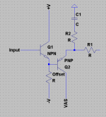
I drew the bias generator for the input purposely like that because for some strange reason I like the way of thinking that the second transistor is there to balance the input transistor for dc conditions - rather like in an LTP. Of course, it's only there to provide a level of temperature compensation for drift in the input device and could in principle be replaced with a single diode for 'good enough' matching. It's part of the fun of DIY that you get to make such personal design decisions.
Tantalum has a mixed record and the quality of these capacitors has changed over the years as has Aluminium electrolytics. Good quality tantalum capacitors can offer some real benefits such as better high frequency performance and much longer life reliability than electrolytics. Some people have reported that Tantalum capacitors sound good (perhaps they introduce a bit of H2) but that's hearsay as far as I am concerned. If you treat them badly, Tantalum capacitors will go up in smoke rather easily whereas aluminium electrolytics are far more forgiving.
I used one simply because it was on hand, and as Andrew points out, I have the feedback shunt capacitor under-sized, so I wanted to add a bit more capacitance there, it really should be bigger. Tantalum caps are relatively small for their capacity and easy to tack one on the backside of a pcb. I was hoping it's use would be controversial...
The main reason C3/10 was not larger is because I was leveraging from the TGM2 pcb layout and already had a capacitor sized for the board. I would suggest a Nichicon MUSE 2,200uF cap here to replace both C10 and C3. In the final application for TGM it is a home theatre surround, where I do not need bass response below 80Hz - 100Hz so it's no limitation there.
If/when I build a dedicated stereo version of TGM3 these things will be addressed along with some other changes (e.g. R10 is unnecessary but was a left-over from TGM2 pcb, I would also explore reducing R20 and R21 to 0R33 or even 0R22 - but first check that the sonics are favourable, pre-driver base stoppers can be halved to 56R, power rails should be at least +/- 36V, at least try out a CFP Singleton input). Were there to be interest from others on the Forum in this design I would be willing to begin such a project sooner, but otherwise it will more likely be in the Fall.
Until I had built this design I had never really accepted the sonic benefits from a triple in protecting the VAS from the output stage, and from driving the output stage from a strong and linear CFP.
Last edited:
Bigun, what confuses me about your input is R3. This effectively makes input impedance 330 ohms; bass would be limited severely I think. If it were not for this I don't think I would have asked.
- keantoken
- keantoken
Member
Joined 2009
Paid Member
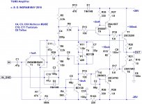
Oh dear ! - my schematic says 360 when it should say 360k - it was actually implemented by putting in parallel a 1M with a 560k because I didn't have a 360k resistor on hand.
Member
Joined 2009
Paid Member

Member
Joined 2009
Paid Member
Agreed - It would make life easier than using a fixed resistor that you have to finalize after you've built the thing (I didn't happen to have any pots of this value to hand)
Member
Joined 2009
Paid Member
Member
Joined 2009
Paid Member
Hi there - good to hear from you.
I'll give it another listen after the thing's proven it can sit stable under power for a few hours. The TGM3 sounds very nice, singleton input and triple output. It's better than the both of TGM1 and TGM2.
But the dc offset is a bit of devil to keep stable, even with a matching diode-wired transistor in the bias circuit it's hard to adequately temperature-compensate the dc operating point. It's not bad, but clearly not as stable as the LTP I've used in my earlier designs. I'll have to give this some further thought.
I'll be glad to see it in service. I'm also looking forward to a break from SS and fiddling around with pcb's. My next project will be hollow state, the base design will have not a semiconductor in sight.
Great job, I wonder how long it'll be until I follow suit with my discarnate Soraya. 🙂
I've got a class A circuit working on my bench right now, I'm using my oscilloscope as a preamp from my soundcard since it doesn't have any gain... I think I will end up building something like my headamp except for speakers...
- keantoken
I've got a class A circuit working on my bench right now, I'm using my oscilloscope as a preamp from my soundcard since it doesn't have any gain... I think I will end up building something like my headamp except for speakers...
- keantoken
Member
Joined 2009
Paid Member
Hi keantoken,
You've been doing a lot of design work these weeks, looks really good. Class A brings a nice simplicity to things, I should have started there in the first place. My Class A project ("Botch Up") is simmering in the background - I'm going to be moving it to some kind of sliding bias because my heatsinks aren't up to the job. I'll do the research whilst I play with some tubes.
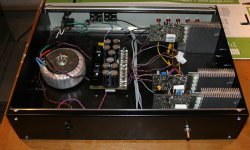
A quick photo of the inside of TGM box...
I think I know what the limitation is on TGM3 dc offset drift with temperature - the current flow through the two transistors (input device and bias device) are too disparate. A higher current through the device in the bias circuit would help but that would lower the input impedance which I'm reluctant to do.
You've been doing a lot of design work these weeks, looks really good. Class A brings a nice simplicity to things, I should have started there in the first place. My Class A project ("Botch Up") is simmering in the background - I'm going to be moving it to some kind of sliding bias because my heatsinks aren't up to the job. I'll do the research whilst I play with some tubes.
A quick photo of the inside of TGM box...
I think I know what the limitation is on TGM3 dc offset drift with temperature - the current flow through the two transistors (input device and bias device) are too disparate. A higher current through the device in the bias circuit would help but that would lower the input impedance which I'm reluctant to do.
Attachments
Could you try something like this for the offset? Tempco would be compensated anyways. It might not be wise to adjust offset using the resistor shown because changing it will give the transistor different load impedance... So it would probably be best to adjust DC with a bias network. Current through Q1 should be close to that through Q2...
I have an Allison design that may be interesting to you, it remains in class A for the first watt or so, but transitions into class AB, non-switching. The Allison gives primarily odd harmonics (of very small magnitude), but I know of a way around this as well. Gah, let's just say there are a billion allison-like ways to do class A and if you tell me what you want, I can probably give you some ideas or inspiration.
- keantoken
Attachments
Last edited:
DC offset is not so much of a problem as you suspect. Speakers will tolerate up to 200mV of offset for long periods without damage or adverse effect on the sound.
You need a bias system which raises the bias voltage towards ground with temp as the circuit warms.
The bias transistor could form this voltage directly, with something like a LED (or diode/LED string) from ground to a 4k7 resistor to neg rail. A 33K resistor from the bottom of theLED/diode string could then bias the input base directly. As the forward voltage drop across the LED/diode string decreases with warmup it would raise the bias point slightly, compensating for the dropping Vbe of the VAS. The bias generator should track the temp of the VAS, but keep it nice and cool anyways....
Oh, according to Roender, R15 is best at 18R, with 1uF across it..... eliminating your base to base cap across the outputs.
Don't dismiss the mosfet. They sound very good with tubes as VAS!
Hugh
Last edited:
Member
Joined 2009
Paid Member
Thanks for diving in with some ideas guys....
This looks pretty neat - but it would be more difficult to implement given the state of my pcb. I may come back to this shortly if I don't find a quick fix
If the odd harmonics are small enough they are of no consequence so this would be a good approach. I thought though, that you had concerns over stability of this output topology ?
unfortunately, the drift I'm seeing is about 3x this level at worse case.
Well I kinda have this in place. I use a diode-wired-transistor in place of an LED though. It's connected to ground on one side and then to the negative rail via resistors on the other. But I've had to use fairly high valued resistors to ensure that the bias is correct - i.e. the base of the input device needs to be held very close to ground (close to Vbe away from ground) so in using a diode-wired-transistor hanging off ground I end up needing a large resistor to keep the bias voltage away sufficiently far from the negative rail. This reduces the current flow through the compensating diode wired transistor to a trickle which makes me wonder if this results in less effective temperature compensation. I don't have a heatsink on the VAS device - this would be easy to fix by popping on one of the small metal sleeve types. I'll try this.
I did look at that, puts a lot of current through the drivers. I'm not sure I need it - maybe you can advise ? Roender was driving 3 output pairs in parallel whereas I only have to drive a single output pair. Roender also has a fancy VAS which perhaps has more drive capability into the drivers too. What I do know, is that this topology sounds absolutely gorgeous.
Yes, that's exactly where I see things heading. I want to cut my teeth first on a nice SE tube amplifier, done in traditional style with transformers and vacuum rectifiers, choke loaded psu and simple two stage architecture. I feel that for me, it is an important part of the DIY journey to have built one of these legendary things (without electrocuting oneself!). But after that I plan to look at hybrids - much has been done in this direction and so there's a lot of material to try out. My aim is tube front end and SS outputs set up in sliding bias Class A. My Botch Up project may help me explore the output structure, based on my version of a Diamond. But that may change if the Allison looks better.
But for now, I have to get the lid screwed down on TGM3 and then start planning out the chasis for Cellini (tube amp) 😀
Could you try something like this for the offset?
This looks pretty neat - but it would be more difficult to implement given the state of my pcb. I may come back to this shortly if I don't find a quick fix
I have an Allison design that may be interesting to you, it remains in class A for the first watt or so, but transitions into class AB, non-switching. The Allison gives primarily odd harmonics (of very small magnitude), but I know of a way around this as well. Gah, let's just say there are a billion allison-like ways to do class A and if you tell me what you want, I can probably give you some ideas or inspiration.
- keantoken
If the odd harmonics are small enough they are of no consequence so this would be a good approach. I thought though, that you had concerns over stability of this output topology ?
DC offset is not so much of a problem as you suspect. Speakers will tolerate up to 200mV of offset for long periods without damage or adverse effect on the sound.
unfortunately, the drift I'm seeing is about 3x this level at worse case.
You need a bias system which raises the bias voltage towards ground with temp as the circuit warms.
The bias transistor could form this voltage directly, with something like a LED (or diode/LED string) from ground to a 4k7 resistor to neg rail. A 33K resistor from the bottom of theLED/diode string could then bias the input base directly. As the forward voltage drop across the LED/diode string decreases with warmup it would raise the bias point slightly, compensating for the dropping Vbe of the VAS. The bias generator should track the temp of the VAS, but keep it nice and cool anyways....
Well I kinda have this in place. I use a diode-wired-transistor in place of an LED though. It's connected to ground on one side and then to the negative rail via resistors on the other. But I've had to use fairly high valued resistors to ensure that the bias is correct - i.e. the base of the input device needs to be held very close to ground (close to Vbe away from ground) so in using a diode-wired-transistor hanging off ground I end up needing a large resistor to keep the bias voltage away sufficiently far from the negative rail. This reduces the current flow through the compensating diode wired transistor to a trickle which makes me wonder if this results in less effective temperature compensation. I don't have a heatsink on the VAS device - this would be easy to fix by popping on one of the small metal sleeve types. I'll try this.
Oh, according to Roender, R15 is best at 18R, with 1uF across it..... eliminating your base to base cap across the outputs.
I did look at that, puts a lot of current through the drivers. I'm not sure I need it - maybe you can advise ? Roender was driving 3 output pairs in parallel whereas I only have to drive a single output pair. Roender also has a fancy VAS which perhaps has more drive capability into the drivers too. What I do know, is that this topology sounds absolutely gorgeous.
Don't dismiss the mosfet. They sound very good with tubes as VAS! Hugh
Yes, that's exactly where I see things heading. I want to cut my teeth first on a nice SE tube amplifier, done in traditional style with transformers and vacuum rectifiers, choke loaded psu and simple two stage architecture. I feel that for me, it is an important part of the DIY journey to have built one of these legendary things (without electrocuting oneself!). But after that I plan to look at hybrids - much has been done in this direction and so there's a lot of material to try out. My aim is tube front end and SS outputs set up in sliding bias Class A. My Botch Up project may help me explore the output structure, based on my version of a Diamond. But that may change if the Allison looks better.
But for now, I have to get the lid screwed down on TGM3 and then start planning out the chasis for Cellini (tube amp) 😀
Last edited:
Member
Joined 2009
Paid Member
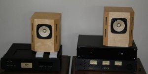
Well, several hours of burn-in and no issues. So listening can start. I've plonked the unit on top of my Dynalab FM tuner for now.
With the higher quality source and my own design of speaker, it really sings. Smoooth.
The missus says it sounds great - who am I to argue 😀
With the higher quality source and my own design of speaker, it really sings. Smoooth.
The missus says it sounds great - who am I to argue 😀
Attachments
Have you tried a resistor between T2's collector and negative rail to try and get the quiescent current through the input and bias transistors equal? Just bypass the bias resistors with something enough to give about 1mA through the bias device.
I spent many grueling hours trying to devise a compensation scheme to make the Allison stable, with low THD into the MHz range, because I'm just a strange one like that. The most effective scheme needs only two resistors and two ceramic caps, and THD is the same throughout the audio spectrum. Klewis used this in his Allison chipamps, which can be found at the end of my Allison thread.
- keantoken
Just to clarify, the Allison is perfectly stable with a reasonable compensation scheme, I was just obsessed with trying to find a better way, since I was trying to develop a HF buffer that I could use around the bench, that would deliver low THD with very high input impedance up to several MHz. At audio any distortions are minimal, except perhaps if you use MOSFETs with gate capacitance, since that adds up in the upper KHz.
- keantoken
- keantoken
Member
Joined 2009
Paid Member
To be honest, I'm kind of done with tweaking TGM3 at this point. At some point in the future I may want to build a SS reference amp (not a hybrid) and I'll want to use something I know sounds good. At that time I may start with TGM3 and start playing with it again. Today I'm listening to my modified TGM2 (tube like sound) in stereo for the first time, playing some Pink Floyd - wonderful !
I do like the idea of this Allison, maybe it's the name, but I will take a further look. Perhaps you might champion a new project, NTP front end, Allison back-end, designed to produce a solid 50W output. Could be your reference amp.
I do like the idea of this Allison, maybe it's the name, but I will take a further look. Perhaps you might champion a new project, NTP front end, Allison back-end, designed to produce a solid 50W output. Could be your reference amp.
- Status
- Not open for further replies.
- Home
- Amplifiers
- Solid State
- designing TGM3 - output Triples