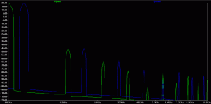
Using two bootstrap caps, one for each side of R15 in Bigun's schematic, decreases 5th harmonics by 11db at 1KHz.
Here is the file I simulated with. Change the extension to .asc.
Just had the thought, using the 2N5087 at the input might be better since it's a quieter transistor. I think it's cheaper than the 5401 too.
- keantoken
Here is the file I simulated with. Change the extension to .asc.
Just had the thought, using the 2N5087 at the input might be better since it's a quieter transistor. I think it's cheaper than the 5401 too.
- keantoken
Attachments
Last edited:
Its definitley not a triple in the sense of the quad circuit, works completly different, I agree that it s performance is quite superior to the ordinary EF. I dont know whether those two emitter resistors you have on the emitters of prediver driver and driver are helping ditortion figures in the sim but in the real world they would actually be detrimental. Small base resistors on the predrivers are usually enough to ensure stability but then again all circuits behave differently. You could also try a cfp input transitor combination, this has many advantages, will drop the THD, both odd and even, sims dont accurately reveal by how much it actually linearises the stage, youll have to test it in the real world.
Member
Joined 2009
Paid Member
Hi homemodder,
The emitter resistors on the drivers were more or less adopted from the Quad design, my assumption was that they may be useful in the battle against stability, if there is one. By including them on the pcb I do force the components to be a little further apart, but they can be replaced by solid links if they are not needed. Their impact on simulated distortion is beneficial, but not so much that it would be sufficient reason to include them.
The cfp input is a definite consideration. Having already heard the improvement of cfp in the front end of TGM2 which as an ltp, I am a big fan. But in the case of the ltp I can see that the cfp does two things,
a) reduces the negative impact of poor device matching (I'm lazy, I don't like to match devices so I don't)
b) improves the linearity of the input and feedback device. Not only does the cfp give 100% local nfb but it also minimizes the current swings through the 'master' device of each compound pair.
For the Singleton I have no devices to match. Also, the error amplification all takes place inside the same device and the differential signal is small because we're using global negative feedback. The potential benefit from a cfp here is therefore much lower. I'll take a look again at the pcb to see how I could squeeze in another device 😀
I was curious and just tested the CFP input. Distortion is decreased by .01%, but the harmonic profile is rather unaffected. If I wanted to reduce distortion without affecting the amp's sound, I would use this.
- keantoken
- keantoken
Member
Joined 2009
Paid Member
Kean,
I've run your simulation file and also see a reduction in the 5th that looks worthwhile, also in the 7th. I duplicated the circuit and ran one at 1kHz and the other at 1.2kHz to separate out the FFT peaks more easily (but it gets confusing after a few peaks).
I've run your simulation file and also see a reduction in the 5th that looks worthwhile, also in the 7th. I duplicated the circuit and ran one at 1kHz and the other at 1.2kHz to separate out the FFT peaks more easily (but it gets confusing after a few peaks).
Attachments
Member
Joined 2009
Paid Member
Which amp sounded the best to your ears, the tgm1 or 2 ??
As built, I preferred TGM1, more musical. But TGM2 is clearer with better bass and high's, it's the amplifier I will use in my HT project.
Last edited:
Member
Joined 2009
Paid Member
I was curious and just tested the CFP input. Distortion is decreased by .01%, but the harmonic profile is rather unaffected. If I wanted to reduce distortion without affecting the amp's sound, I would use this.
- keantoken
I'm more interested in the distortion profile - as we both are 😉
I'm leaning towards the non-CFP for now.
Kean - have you looked at cfp pairs in a Rush configuration ?
Last edited:
Well since you're interested in the profile, I think you should check your Email inbox.
One thing occurs to me. By adding OLG you can't get rid of ANY harmonic. You can only decrease it's magnitude. It might look like it's disappearing if you're pushing harmonics into the noise floor. So really, increasing OLG should be the LAST thing you do when designing an amplifier. Just my questionable thought for the hour.
- keantoken
Member
Joined 2009
Paid Member
I'll check my email when I'm home this evening then...
I agree with the caution on OLG, I am looking for OLG in the range mid 30's to 40 dB max and then apply something in the range of 15dB of nfb. At least for the TGM series. Other designs in the drawing board have no global feedback. Heck I may just build a SET, simple and matches well my interest in simple full range drivers.
p.s. I am running a "modified" TGM2 with 0.3% THD, mostly H2, with some H4.
Last edited:
Try running it at 20V output, 20KHz. Look at the transients produced at crossover. How do we fix that? I think I figured out how once, but I don't remember.
Surprisingly, I thought the worst would happen when the CFP's were forced to turn off. But no, CFP switching is smooth even at 20KHz. Perhaps the degeneration is doing some good here? My past simulations with switching CFP's have been disastrous.
- keantoken
Surprisingly, I thought the worst would happen when the CFP's were forced to turn off. But no, CFP switching is smooth even at 20KHz. Perhaps the degeneration is doing some good here? My past simulations with switching CFP's have been disastrous.
- keantoken
Member
Joined 2009
Paid Member
It's beyond me to understand all the details of cross-over effects, there seems to be much more written on this topic than I have read yet. But there seems to be two camps who have used CFPs at the output - those that had problems and went back to EF feeling that nothing was lost and that EF offers sonics that are just as good - and those that solved their problems (if they had any) and claim that CFP is the best thing they ever did.
Anyhow, one step at a time. I'm going with the CFP drivers, leave the output in EF mode. The drivers should not switch off unless the load is nasty enough to force something nasty?
Interestingly, my simulations don't show the same benefit on reduction of 5th harmonic when repositioning the bootstrap capacitor take off point when compared to Keantokens simulation. I've run them both on the same computer. We both use Spice, but we have slightly different set ups in terms of spice parameters and we are using different device models; I am also running of 26V rails instead of 36V so also using a lower output swing.
However, keantoken emailed me a simulation of TGM3 based on his Rush Cascode (No Tail Pair) front end off of his headphone amp project and it showed very nice results. I don't fully understand this input structure so although he gave me his 'OK' to post it here I need to study it further before I do so 😱
I can get a similar reduction in the 5th harmonic by increasing the current flow through the drivers (as suggested by Andrew T) by reducing R15 to 56R, which gives around 20mA; I also increased the current through the predrivers to around 3mA each.
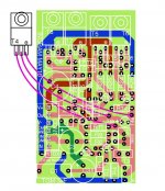
Lastly,the pcb layout had a mistake, the base-collectors of the drivers were transposed so I have had to update the design:
Anyhow, one step at a time. I'm going with the CFP drivers, leave the output in EF mode. The drivers should not switch off unless the load is nasty enough to force something nasty?
Interestingly, my simulations don't show the same benefit on reduction of 5th harmonic when repositioning the bootstrap capacitor take off point when compared to Keantokens simulation. I've run them both on the same computer. We both use Spice, but we have slightly different set ups in terms of spice parameters and we are using different device models; I am also running of 26V rails instead of 36V so also using a lower output swing.
However, keantoken emailed me a simulation of TGM3 based on his Rush Cascode (No Tail Pair) front end off of his headphone amp project and it showed very nice results. I don't fully understand this input structure so although he gave me his 'OK' to post it here I need to study it further before I do so 😱
I can get a similar reduction in the 5th harmonic by increasing the current flow through the drivers (as suggested by Andrew T) by reducing R15 to 56R, which gives around 20mA; I also increased the current through the predrivers to around 3mA each.
Lastly,the pcb layout had a mistake, the base-collectors of the drivers were transposed so I have had to update the design:
Attachments
I once breadboarded a CFP/Allison hybrid. It was hell to get stable, but to this day the sound haunts me. I never heard a more heavenly sound, and it came from a 2.5" speaker set loosely on top of a small wooden trophy base. I posted the design on this forum somewhere.
I think everyone's just scared of the CFP.
- keantoken
I think everyone's just scared of the CFP.
- keantoken
I believe CFP bias current would have an effect on harmonics. Whenever the CFP turns off, you're completing part of some Nth harmonic. Might even be able to watch the harmonics shift if you change the bias. And then, at different output volumes it would change again. I wish there was an easy way to ***** an amp's harmonic profile... 🙁
- keantoken
- keantoken
Member
Joined 2009
Paid Member
Ha ! - what did you really mean ?
So the conclusion is, CFP is for real men, those not afraid of the dark 😀
So the conclusion is, CFP is for real men, those not afraid of the dark 😀
Ha ! - what did you really mean ?
So the conclusion is, CFP is for real men, those not afraid of the dark 😀
If you calculate gm for different currents you lll see that the cfp is even more linear than a differential stage.
But when you start adding degeneration to the master of a CFP to achieve stability, you begin to lose the transconductance and the linearity.....
Hugh
Hugh
Member
Joined 2009
Paid Member
Best performance seems to occur where the amp is on the brink of instability. So, if you know your load you can push things a bit harder. This is an advantage of DIY, we don't have to design the thing to be robust where operating conditions are unknown and uncontrollable.
I dont quite understand this degeneration required by so many, I ve never had to use any for stability. Outside the loop yes, for decreasing the transconductance which is higher than a single transistor and to linearise it even more, the same way it does a single transisostor.
- Status
- Not open for further replies.
- Home
- Amplifiers
- Solid State
- designing TGM3 - output Triples