syn08,
When sound quality has number one priority, besides the gate-source properties, always look at the value of Crss, which is the other main determining factor for linearity. In other cases go for a more loosely defined channel and nasty capacitances, also giving you higher efficiency.
That`s an exceedingly confused statement. L must be short, a number of parameters depend on it, and is beneficial in switching as well, where, however, linear signal transfer is not an issue.The very short channel MOSFETs are a different kettle of fish and have nothing to do with audio and power devices.
When sound quality has number one priority, besides the gate-source properties, always look at the value of Crss, which is the other main determining factor for linearity. In other cases go for a more loosely defined channel and nasty capacitances, also giving you higher efficiency.
syn08,
That`s an exceedingly confused statement. L must be short, a number of parameters depend on it, and is beneficial in switching as well, where, however, linear signal transfer is not an issue.
When sound quality has number one priority, besides the gate-source properties, always look at the value of Crss, which is the other main determining factor for linearity. In other cases go for a more loosely defined channel and nasty capacitances, also giving you higher efficiency.
Lumba, I cannot continue this. You or anybody interested in the topic needs a good book on semiconductor devices physics and start studying the topic. Essntially, no, L must not be necessary short and the channel length also does not have any relationship to linearity. It is the W/L (channel width/length) defining the device current and transconductance. "Short channel" devices have to do with the absolute channel length, usually deep under 1um. At this scale, longitudinal (due to Vds) and transversal (due to Vgs) electric fields cannot be separated, the device has to be considered as a 2D structure. Hence a multitude of new phenomena and a different behaviour.
Very short channel MOSFET devices are constrained to Vds of a very few volts. They are not even close to the requirements for a power device. Audio power devices have channel lengths of 1um and over, not qualifying, from every perspective, as short channel MOSFET devices.
So far, the Gm nonlinearities are DC effects. Cgs, Cgd or Crss, Ciss, etc... have an AC impact and again they have no relationship to the threshold voltage Vt.
Guys, discussing the basic physics of MosFets is not what this thread was meant for. If you have no constructive and direct contributions to the amp itself I would suggest you keep the semiconductor discussion elsewhere really. I find this arguing a tad ridiculous. I have decided to use the Toshiba devices anyway, and don´t give a damn why they behave like they do, nor if they should be labelled as vertical, horisontal or diagonal FETs. I´m only interested in how the amp can be improved.
/Rikard
/Rikard
Last edited:
syn08,
you are right, we should stop this. I consider channel lengths of 1-2 um as short. (As far as I know there are problems with going below 1um in power devices).
You don`t need to reply.
you are right, we should stop this. I consider channel lengths of 1-2 um as short. (As far as I know there are problems with going below 1um in power devices).
You don`t need to reply.
Guys, discussing the basic physics of MosFets is not what this thread was meant for. If you have no constructive and direct contributions to the amp itself I would suggest you keep the semiconductor discussion elsewhere really. I find this arguing a tad ridiculous. I have decided to use the Toshiba devices anyway, and don´t give a damn why they behave like they do, nor if they should be labelled as vertical, horisontal or diagonal FETs. I´m only interested in how the amp can be improved.
/Rikard
Hi Ricard,
You are making a good choice. The Toshiba's are good devices. They are vertical devices which happen to have a lower threshold voltage than the IRF devices. Their good performance has nothing to do with their lower lower threshold voltage. They are well-matched devices and the lower threshold voltage makes them convenient. They do, however command a significantly higher price.
Cheers,
Bob
Rikard,
we can anticipate pretty high distortions in this amp, primarily in the output stage due to a too low quiescent current level and lack of mechanism for linearizing the numerous constantly varying parameters, further worsened by the load, but it´s not convenient to work with this kind of PA-style approach, power dissipation complicates an appropriate type selection and biasing of the plain transistor stages.
we can anticipate pretty high distortions in this amp, primarily in the output stage due to a too low quiescent current level and lack of mechanism for linearizing the numerous constantly varying parameters, further worsened by the load, but it´s not convenient to work with this kind of PA-style approach, power dissipation complicates an appropriate type selection and biasing of the plain transistor stages.
jacco,
I meant the complementary die design, announced in 1977 (I can be wrong). Nice short channel devices you have in stock anyway.
I meant the complementary die design, announced in 1977 (I can be wrong). Nice short channel devices you have in stock anyway.
Hi Ricard,
You are making a good choice. The Toshiba's are good devices. They are vertical devices which happen to have a lower threshold voltage than the IRF devices. Their good performance has nothing to do with their lower lower threshold voltage. They are well-matched devices and the lower threshold voltage makes them convenient. They do, however command a significantly higher price.
Cheers,
Bob
Thanks for the confirmation Bob, I know several high quality amps that use these so that wasn´t a hard decision to make. How to improving the distorsion figures is what puzzles me. The speed I think is ok now, so that leaves me two choices really, have another go with error correction or try something completely different, like CFP style output. I did som sims, but this output ended up with 5-8 times higher THD. Could be down to me not having worked with this kind of outputs enough. I have built a better prototype now however, so the EC network might work better than the last attempt. I simply could not get it stable. But as it sims so beautifully I would love to get it working. Distorsion certainly drops in the sims when I use EC.
Rikard,
we can anticipate pretty high distortions in this amp, primarily in the output stage due to a too low quiescent current level and lack of mechanism for linearizing the numerous constantly varying parameters, further worsened by the load, but it´s not convenient to work with this kind of PA-style approach, power dissipation complicates an appropriate type selection and biasing of the plain transistor stages.
I agree with you that the output is the main source for distorsion, and I have nothing against running it at a fairly high bias, but it would still be nice getting the distorsion down in a smarter way. It isn´t bad now either, but anything could be improved of course. Initial CFP sims turned out to be a sure way to much higher distorsion, so I dropped that idea. If somebody knows a really good CFP output topology I´m willing to try it for real. I can measure distorsion fairly accurate so once a prototype is built we will know right away which version is better.
🙂
Thanks for the confirmation Bob, I know several high quality amps that use these so that wasn´t a hard decision to make. How to improving the distorsion figures is what puzzles me. The speed I think is ok now, so that leaves me two choices really, have another go with error correction or try something completely different, like CFP style output. I did som sims, but this output ended up with 5-8 times higher THD. Could be down to me not having worked with this kind of outputs enough. I have built a better prototype now however, so the EC network might work better than the last attempt. I simply could not get it stable. But as it sims so beautifully I would love to get it working. Distorsion certainly drops in the sims when I use EC.
I agree with you that the output is the main source for distorsion, and I have nothing against running it at a fairly high bias, but it would still be nice getting the distorsion down in a smarter way. It isn´t bad now either, but anything could be improved of course. Initial CFP sims turned out to be a sure way to much higher distorsion, so I dropped that idea. If somebody knows a really good CFP output topology I´m willing to try it for real. I can measure distorsion fairly accurate so once a prototype is built we will know right away which version is better.
🙂
Hi Rikard,
I do not recommend you use a CFP output stage. They can have serious stability problems and they sometimes cross over too abruptly - this applies to BJT output stages as well. This is an area where Doug Self and I do not agree.
I don't remember your schematic, but in general, if you are building an amplifier less than 150W 8 ohms and will not be abusing it, use two pairs of the Toshiba MOSFETs and bias each pair at about 150 mA (300 mA total class AB bias). If the rest of your amp design (IPS, VAS, drivers) is good, and your NFB gain crossover is, say, between 500 kHz and 1 MHz, and you have it stable in every way, you should be able to do better than about 0.03% THD-20 into 8 ohms (without EC) with fairly conventional feedback compensation.
Cheers,
Bob
Rikard,
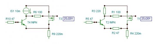
I do warmly recommend the CFP output, FETs do not suffer from minority carrier saturation like BJTs in class AB. Stability may be a problem. You could contemplate these possibilities. All resistor values are subject to change, some of them need to be determined empirically.
I do warmly recommend the CFP output, FETs do not suffer from minority carrier saturation like BJTs in class AB. Stability may be a problem. You could contemplate these possibilities. All resistor values are subject to change, some of them need to be determined empirically.
Attachments
Hi Rikard,
I do not recommend you use a CFP output stage. They can have serious stability problems and they sometimes cross over too abruptly - this applies to BJT output stages as well. This is an area where Doug Self and I do not agree.
I don't remember your schematic, but in general, if you are building an amplifier less than 150W 8 ohms and will not be abusing it, use two pairs of the Toshiba MOSFETs and bias each pair at about 150 mA (300 mA total class AB bias). If the rest of your amp design (IPS, VAS, drivers) is good, and your NFB gain crossover is, say, between 500 kHz and 1 MHz, and you have it stable in every way, you should be able to do better than about 0.03% THD-20 into 8 ohms (without EC) with fairly conventional feedback compensation.
Cheers,
Bob
Thanks Bob, sounds pretty much like the amp is at the moment. The schematic is a classic dual diff input, very simple VAS and driver finished with two pairs of Toshiba´s (stabilized using your brilliant gate Zobel´s! 🙂 ) which I by the way had some trouble matching for similar bias. I guess that would affect distorsion too as the non linear area is supposedly wider, right?
The sims are done using the IRF devices though, I don´t have the Toshiba´s in my database. Too bad!
Are there any other major tweaks that can reduce distorsion? Like cascoding something more than the VAS. I tried simming the input and VAS only and actually read higher THD than with the output involved. 😕
/Rikard
Attachments
Rikard,
FETs do not suffer from minority carrier saturation like BJTs in class AB.
You can't resist, can't you
 That animal doesn't exist, you probably mean "charge storage" or "excess minority carriers recombination". And has nothing to do with class AB in particular, it happens in class A and switching as well.
I do not recommend a CFP output configuration; there are no universal recipe to keep it stable. The amateur DIYer usually ends up patching caps here and there, the end result being usually worse than what you get with (e.g.) a Locanthi triple configuration.
syn08,
I like when you are watchful. Of course, "minority carrier saturation" is a meaningless expression, saying excess minority carrier concentration, causing saturation cut-off problems, hopefully, would have been closer to the truth.
It is possible to achieve sufficient stability with carefully chosen devices. I agree, patching caps here and there is a serious setback, whereby some (or most) of the advantages of this great configuration are lost. So using BJT slaves in class AB is not adequate.
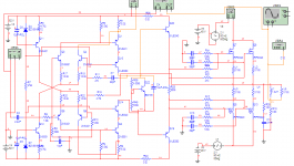
Just playing around with some sims again. This input/VAS topology looks like a better one compared to the "old" one in this thread. The thought is to combine this with the J201/K1530 output stage later once I get it stable. Problem now is I can´t find the cause for oscillations, the common cap in the NFB loop won´t help.
Feel free to come up with a good solution! 😀
Feel free to come up with a good solution! 😀
Attachments
common feedback cap isn't a good solution for oscillation anyway. try compensation caps on Q8, Q9. also double check and make sure the circuit isn't inverting. it looks like it is
Last edited:
Low Threshold effects at higher power Class AB
Hello Syn08 and Bob,
Regarding my earlier post a few posts back about using the lower threshold types of 2SK1530 etc (O grade) was I wondered if they would have "less discontinuity" in Class B at the crossover region.
In Class AB at 150mA Iq this probably isn't a issue at low power but as it moves to high powers in Class B I wonder if the lower threshold would help ?
Laterals are a bad example (whilst having low threshold) as they have lower gm than Verticals to start with - so this isn't a fair comparison THD wise.
PS. Are you saying that the sub threshold conduction takes care of this regardless of the higher threshold ?
Apologises if I don't understand. Just trying to learn.
Thanks
This is a very good description. I guess what you mean by "transconductance mismatch in the crossover region" is actually the subthreshold (exponential) mismatch. This mechanism (actually the subthreshold conduction slope gap to the theoretical 60mV/decade) is of course independent to the threshold voltage value as well.
Hello Syn08 and Bob,
Regarding my earlier post a few posts back about using the lower threshold types of 2SK1530 etc (O grade) was I wondered if they would have "less discontinuity" in Class B at the crossover region.
In Class AB at 150mA Iq this probably isn't a issue at low power but as it moves to high powers in Class B I wonder if the lower threshold would help ?
Laterals are a bad example (whilst having low threshold) as they have lower gm than Verticals to start with - so this isn't a fair comparison THD wise.
PS. Are you saying that the sub threshold conduction takes care of this regardless of the higher threshold ?
Apologises if I don't understand. Just trying to learn.
Thanks
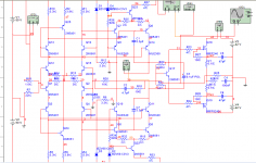
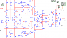
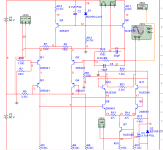
Don't you need some kind of buffering stage between VAS and OPS with regards to the capacitance of the MOSFETs? Or maybe a cascoded OPS?Here´s another version with everything cascoded for maximum speed. I added a full differential VAS for lower distorsion. Suggestions appreciated! 🙂
There is the entire error correction network between the VAS and OPS so I don´t understand what you mean?
I did try the VAS directly to a standard OPS with very good results too, so if the bias of the VAS transistors is cranced up to let´s say 25 mAs or so it works very well.
🙂
I did try the VAS directly to a standard OPS with very good results too, so if the bias of the VAS transistors is cranced up to let´s say 25 mAs or so it works very well.
🙂
- Status
- Not open for further replies.
- Home
- Amplifiers
- Solid State
- Designing amp with 2SJ201/2SK1530